Smart Breakage Detection with Auto Power Cut System for Local Transmission Lines using LoRa (ELECTROFF SYSTEM)
Introduction
Electrical distribution lines are exposed to various faults such as wire breakage, pole fall and line damage due to environmental conditions, accidents and natural disasters. These faults can lead to electric shocks, fire hazards, equipment damage and delays in fault identification. To improve safety and reduce response time, a smart monitoring and protection system is proposed.
Problem Statement
Electrical transmission and distribution lines are frequently affected by wire breakage, pole fall, storms, accidents and natural disasters. When a live wire falls on the ground, it can cause electric shocks, fire accidents, loss of human life and damage to public property. In rural and agricultural areas, fallen wires also pose a serious threat to farmers and livestock.
Currently, fault detection and power shutdown often depend on manual inspection, which increases response time and accident risk. Therefore, there is a need for an intelligent system that can automatically detect wire breakage and pole fall, instantly alert maintenance personnel and safely disconnect the affected power line to prevent accidents and improve public safety.
Proposed Solution
A smart monitoring and protection system that detects wire breakage and pole fall in real time using sensors, transmits fault information wirelessly, sends instant SMS alerts and automatically isolates the affected section to improve safety and reliability.
System Overview
The proposed system consists of a Transmitter (TX) Unit installed on selected distribution poles and a Receiver (RX) Unit installed near the transformer or monitoring location. The system continuously monitors current flow, voltage conditions, and pole inclination using sensors.
The collected data is processed by a microcontroller and transmitted wirelessly through a long-range communication module. When a fault is detected, the receiver unit generates alerts, sends SMS notifications and activates an automatic power isolation mechanism.
Working Principle
- Assume the transformer as the Receiver Pole (Rx) and the street pole as the Transmitter pole (Tx).
- If the wire is cut, the Current sensor at Tx detects no current and sends this to the microcontroller.
- The microcontroller sends signals through LoRa to the Rx pole(Transformer) , which then gives outputs.
- Outputs are: SMS alert, display on monitor, and MCCB to switch off the faulty line/Servo mech to cut the power line.
Additionally, A tilt sensor detects pole fall, the microcontroller cuts current, and power backup is given by a rechargeable battery from the Output transformer line via AC to DC
Step 1: Data Monitoring
The transmitter unit continuously monitors:
- Current flow in the distribution line
- Line voltage condition
- Pole tilt angle
The sensor data is processed by the microcontroller.
Step 2: Fault Detection
When any of the following conditions occur:
- Wire Breakage
- Pole Fall
- Abnormal Current Condition
- The microcontroller identifies the fault condition.
Step 3: Wireless Communication
The detected fault information is transmitted from the TX Unit to the RX Unit using long-range wireless communication.
Step 4: Alert Generation
After receiving the fault information, the RX Unit:
- Displays fault status on LCD
- Activates Red Warning LED
- Activates Buzzer Alarm
- Sends SMS alerts to EB Office and maintenance personnel
Step 5: Automatic Power Isolation
The isolation output is activated automatically to disconnect the affected section and prevent electrical hazards.
Step 6: Reset Verification
After maintenance:
- Operator presses Reset Button
- System rechecks sensor status
- If fault exists, isolation remains active
- If fault is cleared, power is restored safely.
Connections
STEP 1 – TX ESP32 Power Connection
- ESP32 VIN → 5V
- ESP32 GND → GND
Verify that the ESP32 powers on successfully.
STEP 2 – Voltage Sensor Connection
- Voltage Sensor VCC → ESP32 3.3V
- Voltage Sensor GND → ESP32 GND
- Voltage Sensor OUT → GPIO32
STEP 3 – Tilt Sensor Connection
- Tilt Sensor VCC → ESP32 3.3V
- Tilt Sensor GND → ESP32 GND
- Tilt Sensor OUT → GPIO34
STEP 4 – Current Sensor (ACS712) Connection
- ACS712 VCC → 5V
- ACS712 GND → GND
- ACS712 OUT → GPIO35
Power Line Connection:
Power Line → ACS712 IP+ → ACS712 IP− → Load
STEP 5 – HC-12 / LoRa Connection (TX Side)
- HC-12 TX → GPIO16
- HC-12 RX → GPIO17
- HC-12 VCC → 5V
- HC-12 GND → GND
TX Node Setup Completed.
STEP 6 – RX ESP32 Power Connection
- ESP32 VIN → 5V
- ESP32 GND → GND
STEP 7 – HC-12 / LoRa Connection (RX Side)
- HC-12 TX → GPIO26
- HC-12 RX → GPIO25
- HC-12 VCC → 5V
- HC-12 GND → GND
STEP 8 – LCD Connection
- LCD VCC → 5V
- LCD GND → GND
- LCD SDA → GPIO21
- LCD SCL → GPIO22
STEP 9 – Servo Motor Connection
- Servo Signal → GPIO33
- Servo VCC → External 5V Supply
- Servo GND → GND
STEP 10 – Buzzer Connection
- Buzzer Positive → GPIO27
- Buzzer Negative → GND
STEP 11 – Push Button Connection
- One Terminal → GPIO13
Other Terminal → GND
STEP 12 – GSM
- SIM900A TX → ESP32 GPIO16 (RX)
- SIM900A RX → ESP32 GPIO17 (TX)
- SIM900A GND → ESP32 GND
- SIM900A VCC → External 12V/2A Adapter (or as specified by your SIM900A board)
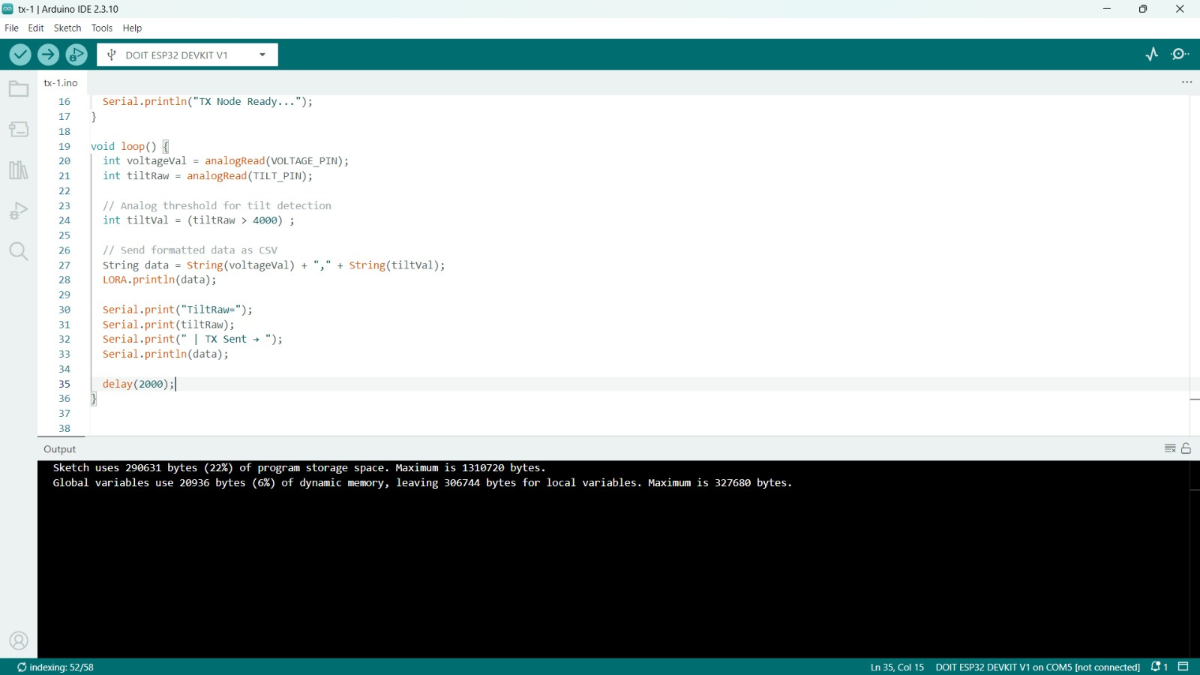
STEP 13 – Upload TX Code
Upload the transmitter code to the TX ESP32.
Expected Serial Monitor Output:
- TX Sent: 3500,0,1
STEP 14 – Upload RX Code
Upload the receiver code to the RX ESP32.
Expected LCD Display:
- RX Node Ready
STEP 15 – System Testing
Normal Condition:
- Voltage Present
- Tilt = 0
- Current = 1
Result:
- Servo OFF
- Buzzer OFF
Wire Cut Detection:
- Current becomes 0
Result:
- Servo rotates to 60°
- Buzzer ON
- SMS Alert Sent
- Blynk Notification Sent
Pole Fall Detection:
- Tilt Sensor activated
Result:
- Servo ON
- Buzzer ON
- SMS Alert Sent
System Reset:
- Press Reset Button
Result:
- Servo OFF
- Buzzer OFF
- System returns to Normal Mode
System Workflow
The proposed system consists of a Transmitter (TX) Unit installed on selected distribution poles and a Receiver (RX) Unit installed near the transformer. The TX Unit continuously monitors current flow, voltage level and pole tilt using sensors. The collected data is processed by a microcontroller and transmitted wirelessly to the RX Unit through long-range communication. When a wire breakage, pole fall or abnormal electrical condition is detected, the RX Unit immediately receives the fault information and activates a warning buzzer, red LED indicator and LCD display. At the same time, a GSM module sends an SMS alert to the Electricity Board (EB) office and maintenance personnel. The system then triggers an isolation mechanism to disconnect the affected line section and prevent electrical hazards. After the fault is repaired, the operator can press the reset button, allowing the system to verify the line condition. If no fault is detected, power is safely restored; otherwise, the isolation remains active until the fault is cleared.
.jpeg)
Block Diagram
The proposed system consists of a Transmitter (TX) Unit and a Receiver (RX) Unit connected through long-range LoRa communication. The TX Unit is installed on the monitoring pole and continuously observes line conditions using voltage/current sensors and a tilt sensor. The sensor data is processed by a microcontroller, which detects wire breakage, pole fall or abnormal electrical conditions. The fault information is then transmitted wirelessly to the RX Unit through LoRa communication.
The RX Unit receives the fault data and processes it using a microcontroller. Upon fault detection, the system activates a buzzer, emergency warning light and LCD display to provide local fault indication. Simultaneously, a GSM module sends SMS alerts to the Electricity Board (EB) and maintenance personnel. The RX Unit also controls a servo-based isolation mechanism or MCCB interface to safely disconnect the affected line section and prevent electrical hazards. A reset button is provided to verify fault clearance before restoring power. The system additionally supports IoT dashboard integration for remote monitoring and fault management.
.png)
Schematic
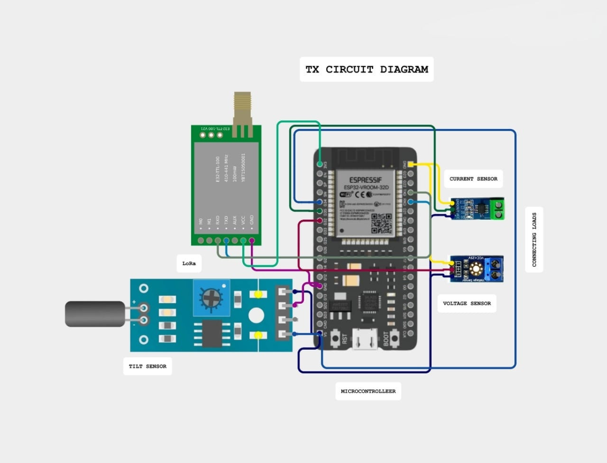
Transmitter (TX) Unit
The TX Unit is installed on the monitoring pole and continuously monitors the electrical distribution line using voltage/current sensors and a tilt sensor. The sensor data is processed by the ESP32 microcontroller to identify wire breakage, current interruption, voltage abnormalities and pole fall conditions. The TX Unit is powered through a battery-backed power supply system and transmits fault information wirelessly to the RX Unit using the HC-12 (SI4463) communication module.
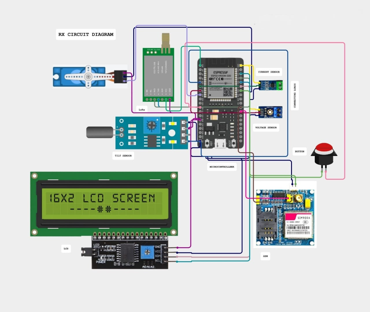
Receiver (RX) Unit
The RX Unit is installed near the transformer and receives fault information from the TX Unit through wireless communication. The ESP32 microcontroller processes the received data and activates the LCD display, buzzer and emergency warning light to indicate the fault condition. Simultaneously, the SIM900 GSM module sends SMS alerts to the Electricity Board (EB) and maintenance personnel. The RX Unit also controls the isolation mechanism through a servo motor or MCCB interface to safely disconnect the affected line section. A reset button is provided to verify fault clearance and restore power only after safe operating conditions are confirmed.
Methodology
Step 1: Monitor current, voltage and pole tilt using sensors.
Step 2: Process sensor data using microcontroller.
Step 3: Detect wire breakage or pole fall conditions.
Step 4: Transmit fault information through LoRa communication.
Step 5: Generate alerts using buzzer, LED and LCD.
Step 6: Send SMS notification to EB office using GSM.
Step 7: Activate isolation mechanism for safe power cut.
Step 8: Verify fault clearance and restore power through reset operation.
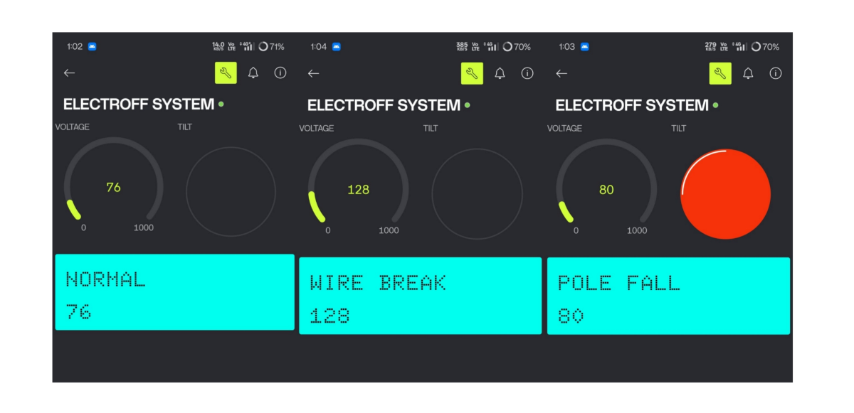
Output
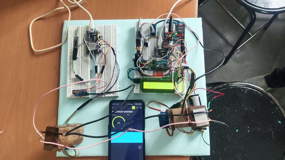
IoT Blynk Dashboard
The IoT Blynk Dashboard enables real-time monitoring of current, voltage, pole status, fault alerts and power isolation status. It provides remote access to system information, helping maintenance personnel identify and respond to faults quickly.
Benefits and Social Impact
The Smart Breakage Detection with Auto Power Cut System using LoRa provides significant benefits for public safety, electrical infrastructure protection and efficient fault management. The system can help prevent electric shock accidents caused by broken or fallen live wires by automatically isolating the affected line section and generating immediate alerts.
In rural areas, the system improves safety for farmers, livestock and residents who may unknowingly come into contact with damaged electrical lines. In agricultural fields, it reduces the risk of electrical accidents near irrigation systems and farming activities. In urban environments, it helps protect pedestrians, motorists and public infrastructure from hazards caused by fallen poles and broken conductors.
The system is also highly beneficial during natural disasters such as cyclones, storms, floods and heavy rainfall, where electrical poles and conductors are vulnerable to damage. Real-time fault detection and automatic power isolation can reduce secondary accidents, fire hazard and equipment damage during emergency situations.
By providing instant wireless communication, GSM alerts, local alarms and remote monitoring through an IoT dashboard, the system enables faster maintenance response and reduces downtime. The proposed solution supports safer electrical distribution networks, improves reliability, reduces manual inspection efforts and contributes to the development of smart and resilient power infrastructure.
Key Features
- Real-Time Fault Detection
- Wire Breakage Monitoring
- Pole Fall Detection
- Long-Range Wireless Communication
- GSM Alert Notification
- Automatic Power Isolation
- Manual Reset Verification
Low Cost and Scalable Design
Applications
- Rural Distribution Networks
- Urban Distribution Networks
- Agricultural Lands and Irrigation Areas
- Disaster-Prone Regions
- Smart Grid Infrastructure
- Industrial Power Distribution Systems
- Remote Village Electrification Projects
- Public Safety Monitoring Systems
Hazards Prevented
- Electric Shock Accidents
- Human Fatalities Due to Fallen Wires
- Livestock Electrocution
- Fire Hazards Caused by Electrical Faults
- Equipment Damage Due to Delayed Fault Detection
- Accidents During Cyclones and Storms
- Unauthorized Contact with Live Conductors
- Infrastructure Damage Escalation
Novelty of the Project
- Real-time fault detection
- Long-range wireless monitoring
- Automatic power isolation
- GSM alert notification
- Fault verification before power restoration
- Suitable for rural and agricultural areas
Technical Challenges Addressed
- Delayed fault identification
- Lack of remote monitoring
- Unsafe manual fault detection
- Power restoration without fault verification
- Communication limitations in rural areas
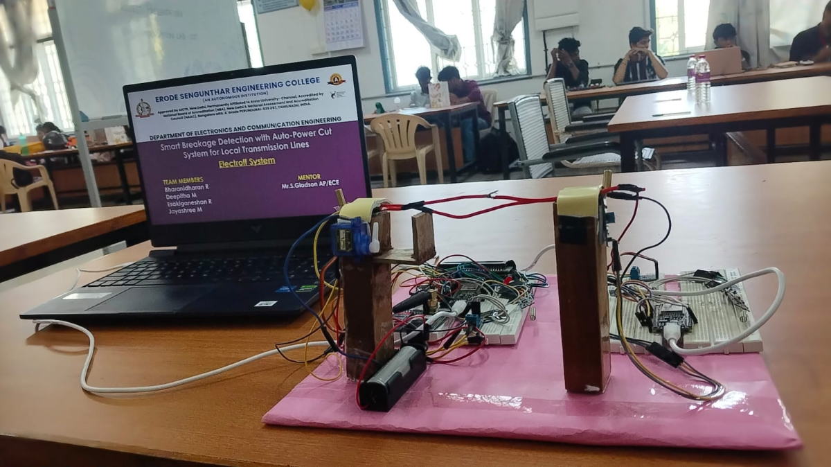
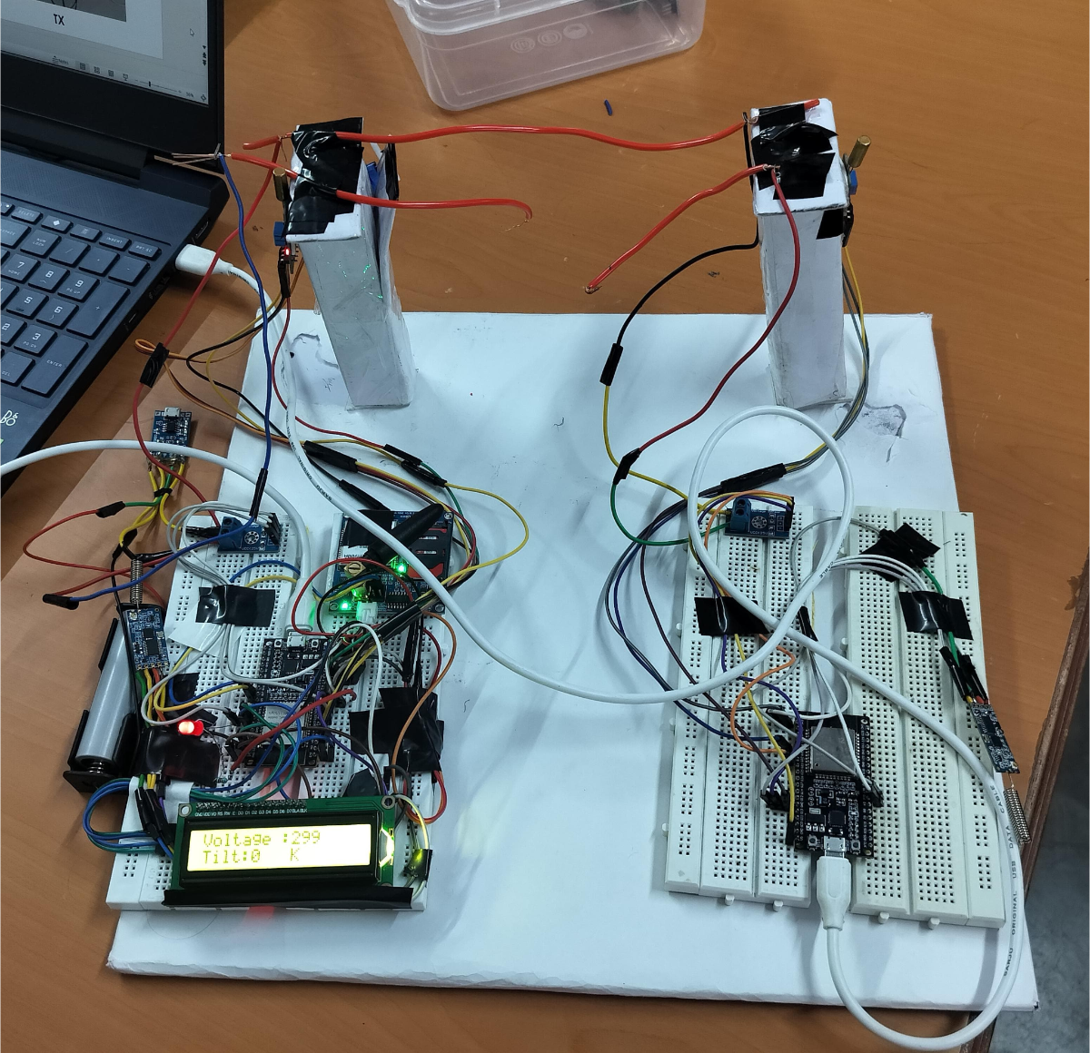
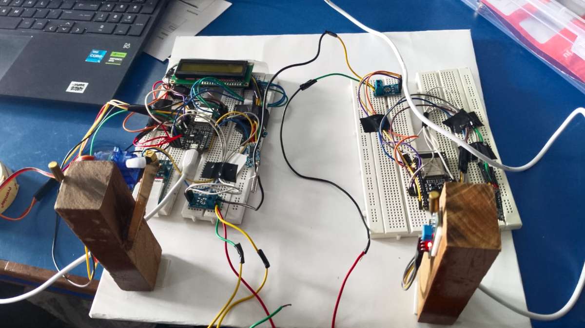
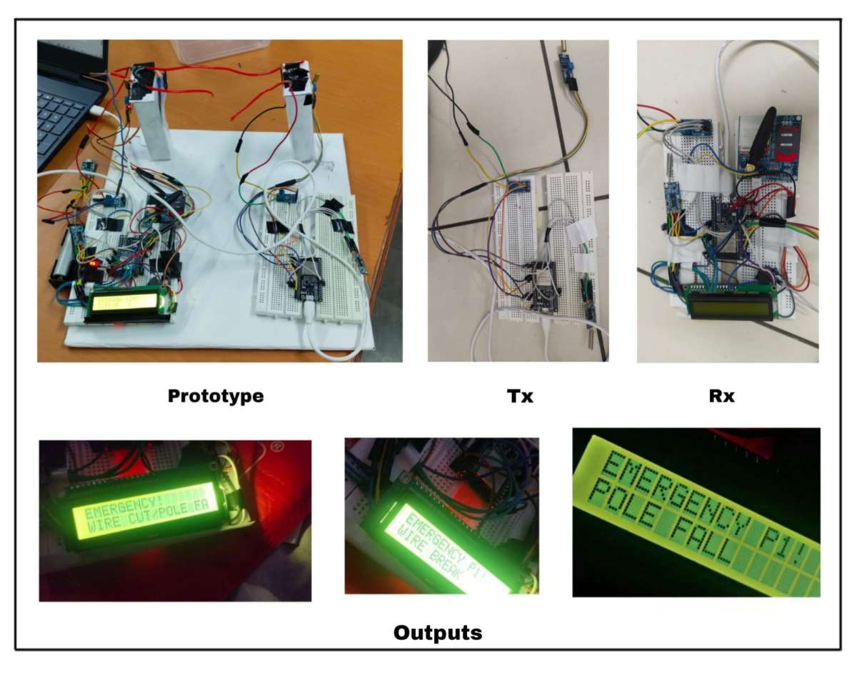
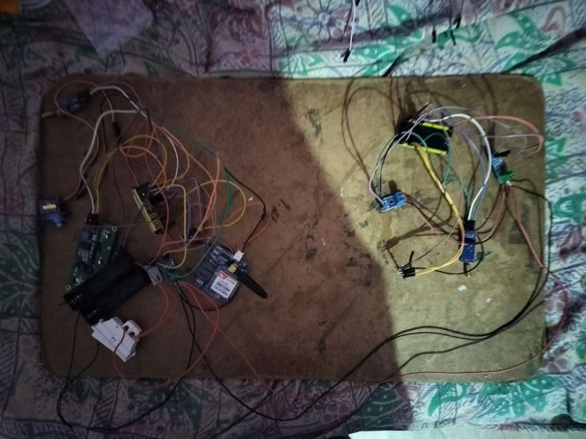
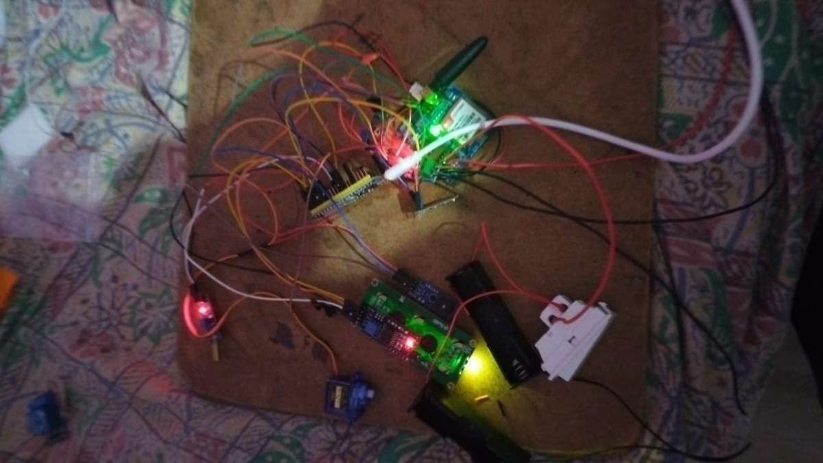
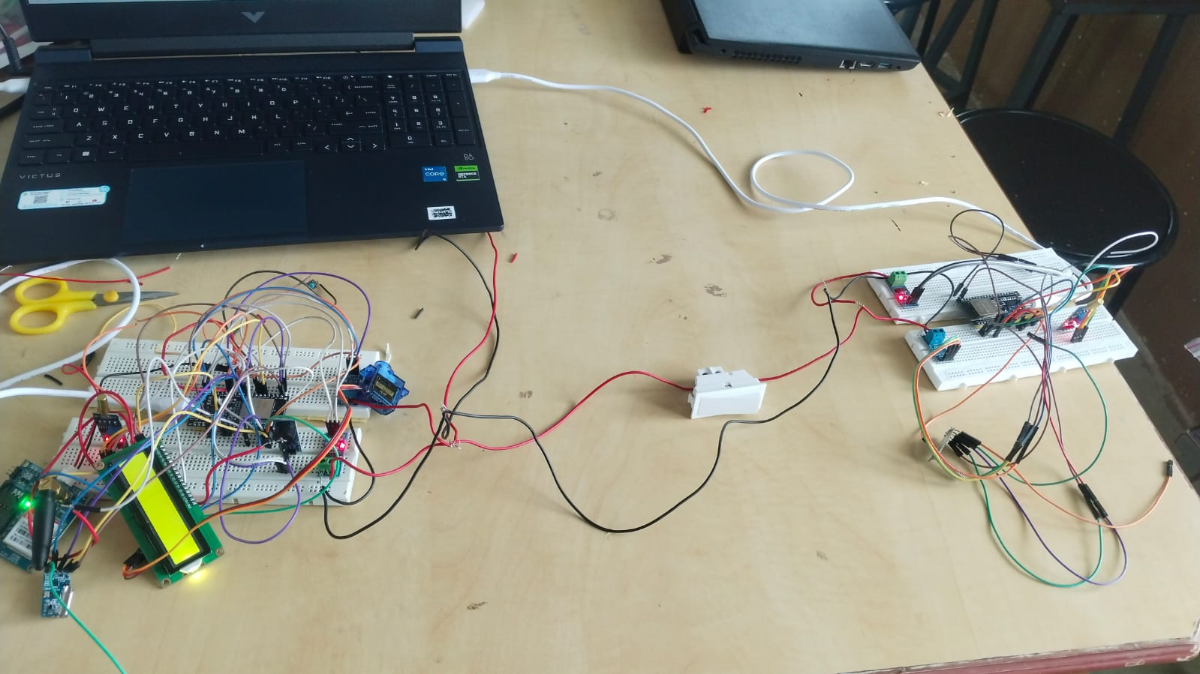
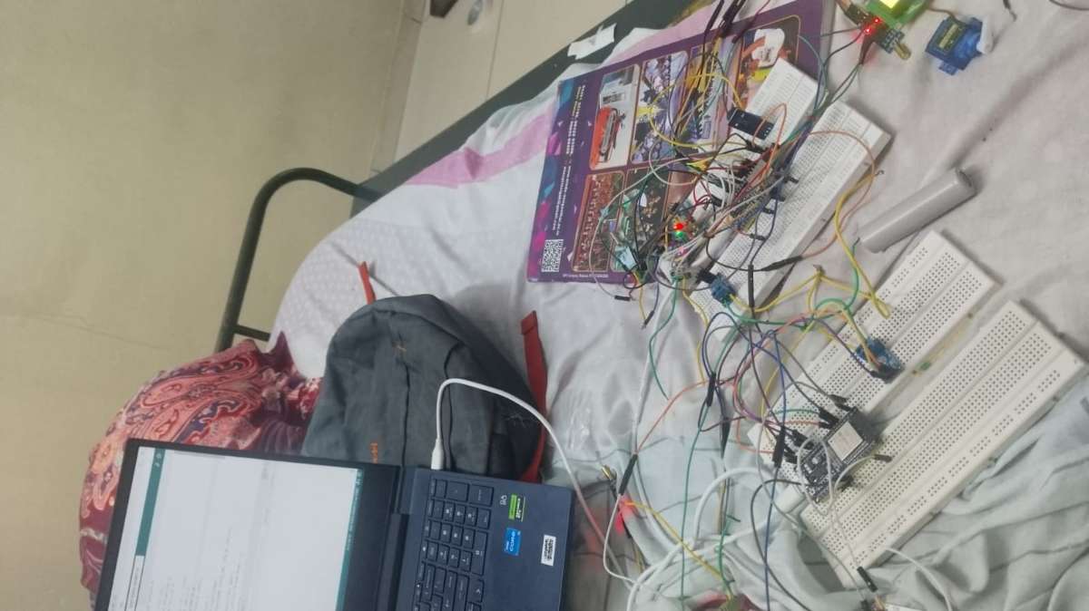
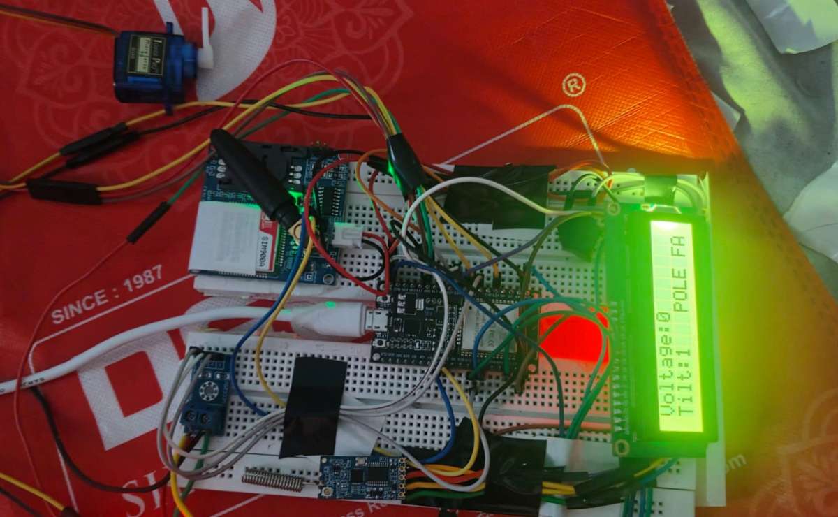
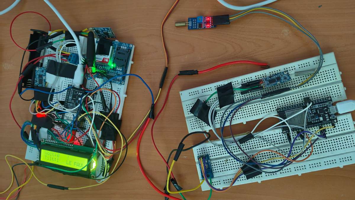
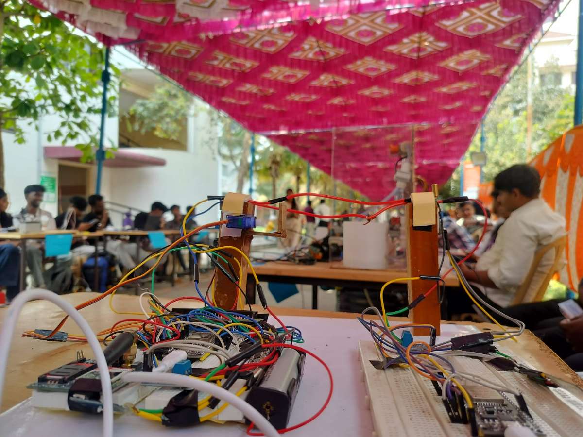
Project Building Glimpse
.jpeg)
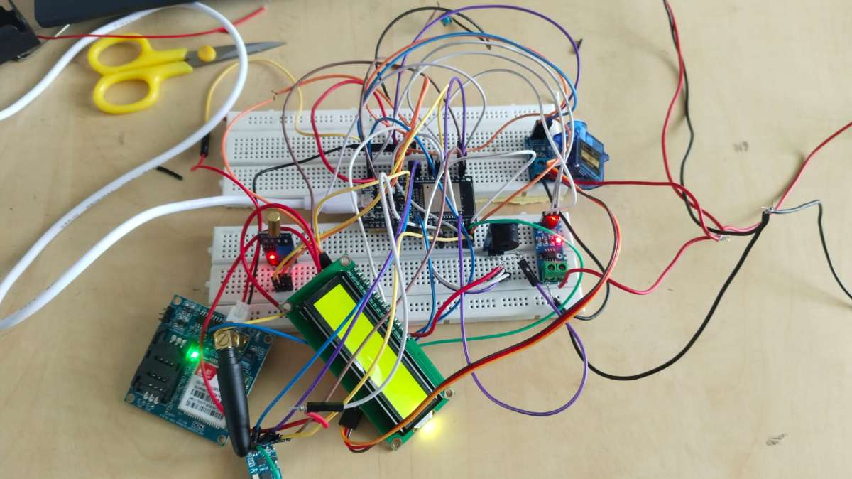
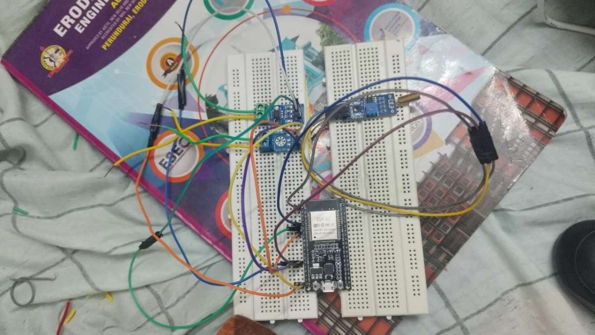
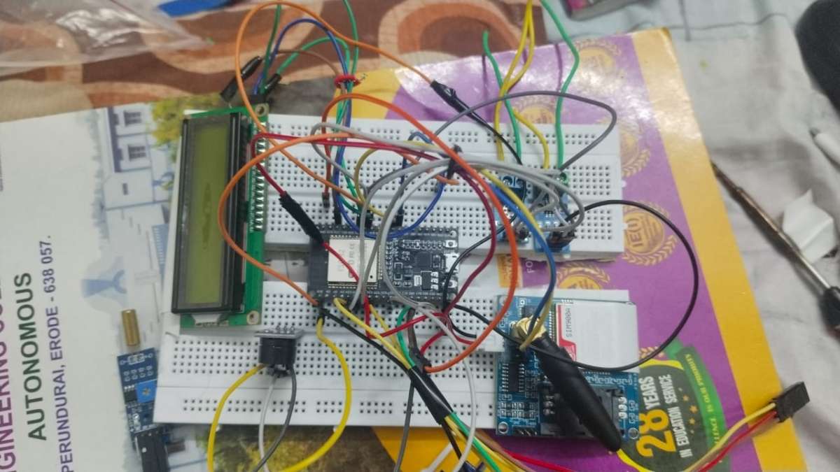
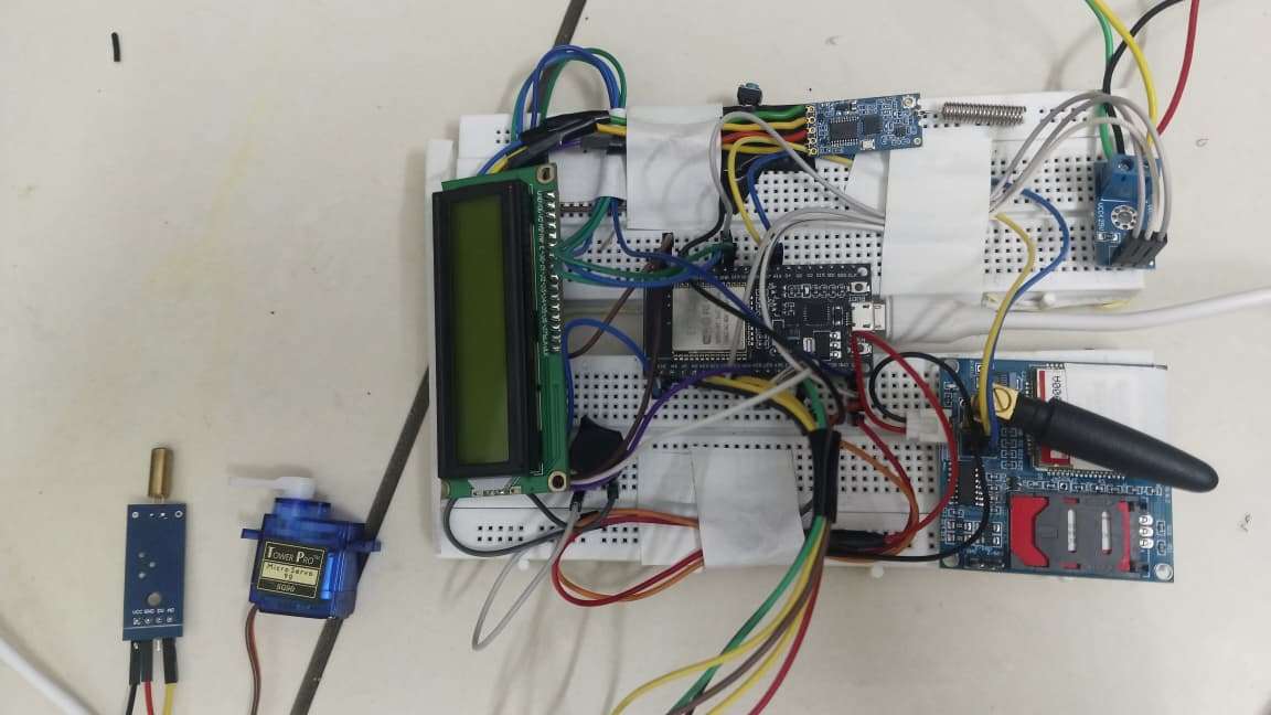
.jpeg)
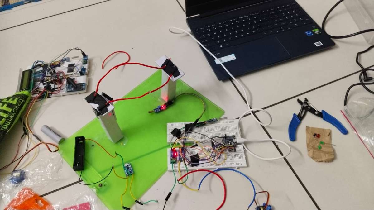
.jpg)
Innovation
The system combines fault detection, long-range wireless communication, remote alerting, automatic power isolation and fault verification into a single low-cost platform suitable for rural and urban distribution networks.
Expected Outcome
The system improves electrical safety, reduces accident risks, minimizes maintenance response time and enables faster restoration of power during fault conditions.
Conclusion
The proposed Smart Breakage Detection with Auto Power Cut System provides a reliable, low-cost and scalable solution for real-time fault monitoring, remote alert generation and automatic power isolation, enhancing the safety and efficiency of electrical distribution networks.
Youtube Video Link
Drive Link (Full Details)
https://drive.google.com/drive/folders/1_kfd6snUCCmo6WxGQ4AtU_htMoNNkEUu