Components short description
ESP32 microcontroller — the project brain: runs control code, reads sensors, runs lightweight Edge-AI models and handles Wi-Fi/Bluetooth; LoRa Si4463 — long-range radio module to send low-bandwidth alerts between poles or to a local gateway when GSM/Internet is unavailable; Voltage sensor — measures line voltage to detect abnormal drops or spikes; Current sensor — measures line current to detect open circuits/breaks or sudden surges; Tilt sensor — detects pole tilt/fall so the system knows a pole has collapsed; GSM 900L — cellular modem to send SMS alerts to the electricity board when needed; Buzzer — local audible alarm for on-site warning; Lithium battery 3700 mAh & battery holder & lithium battery module — mobile power source and protection/charging circuit so the unit keeps running during outages; Servomotor 90° — used for small relay/lock actuation or mechanical switching where precise motion is needed; Breadboard & wires — prototyping platform and wiring connections; Button (reset) — manual reset or test trigger; 16×2 LCD display — local status display for voltage/current/alerts; Wires — interconnections; Battery holder — secure mounting for the battery.
TX SIDE – Step-by-Step (Transmitter Unit)
(Mounted on the transmission pole)
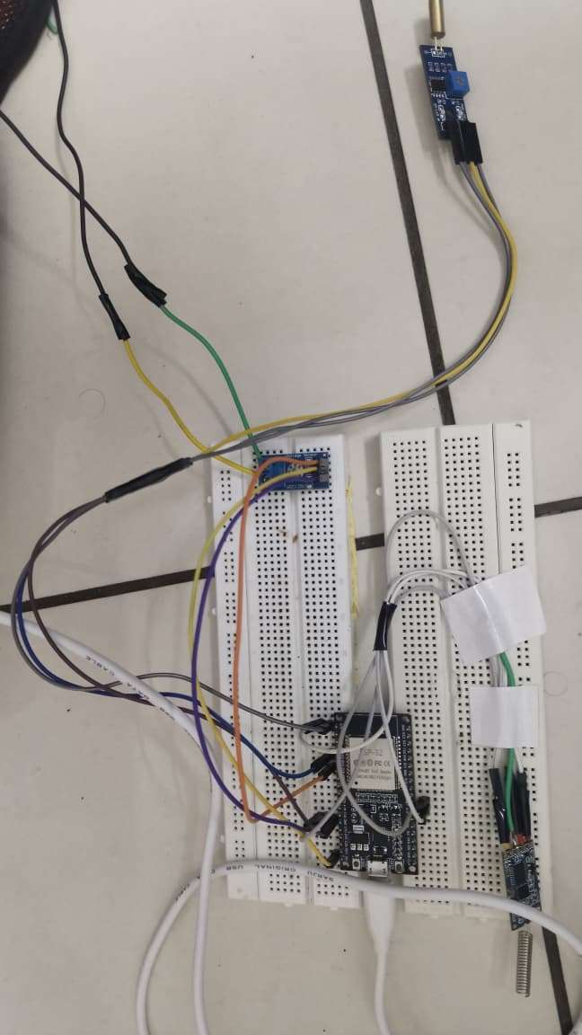
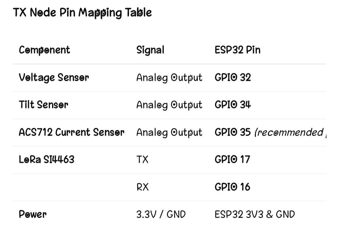
1. ESP32 Setup
We first placed the ESP32 on the TX board. This microcontroller reads all sensor data and sends it wirelessly to the RX side using LoRa.
2. Sensor Connections
Tilt Sensor: Fixed on the pole to detect pole leaning/fall.
Voltage Sensor: Connected to measure the line voltage level.
Current Sensor: Added to monitor the flow of current in the line.
3. LoRa (SI4463) Communication
We connected the LoRa module to ESP32 through SPI pins.
This sends real-time fault data (tilt/voltage/current) to the RX side over long distance.
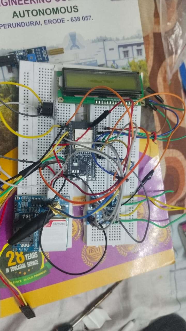
4. GSM Module (SIM900A)
The GSM module is added for emergency SMS alerts to EB office when a break or fall is detected.
5. Buzzer Alert
A buzzer is attached for local alarm on the pole, giving continuous high/low tones during fault.
6. Power System
3700mAh Lithium battery + protection module
Battery holder + wiring
Provides stable power to ESP32, sensors, GSM, and LoRa.
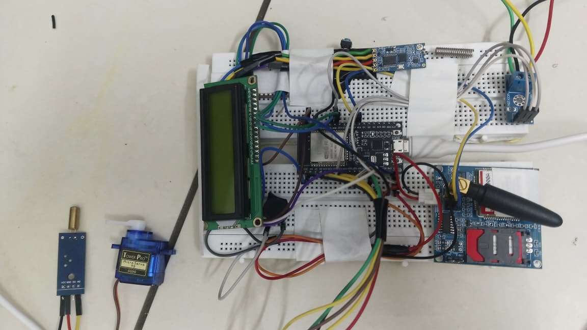
7. Final Assembly
All components are arranged on breadboard / PCB, wires connected, and the unit is mounted on the test pole. Sensors Fully covered with ip65 mounted box
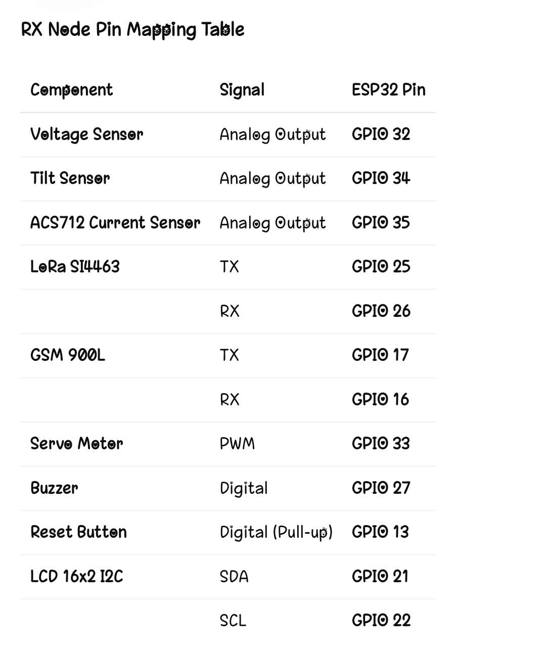
RX SIDE – Step-by-Step (Receiver + Auto Powercut Unit)
1. ESP32 Setup
Another ESP32 is used at the substation/control side to receive LoRa signals.
2. LoRa Receiver Connection
The RX LoRa module receives sensor data sent from the pole.
This data is decoded by ESP32.
3. Sensor Inputs (Optional Monitoring)
RX side also includes:
Tilt sensor
Voltage sensor
Current sensor
This allows double confirmation and backup monitoring on the control side.
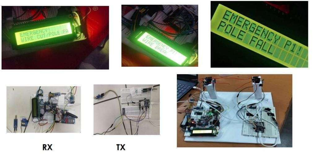
4. Display Monitoring
A 16x2 LCD is connected to show:
Voltage
Current
Pole Status (Normal / Tilt / Break)
Connection Quality
5. Servo Motor / MCCB Mechanism
Based on the alert:
The servo motor physically triggers the switch to cut supply
OR
MCCB mechanism is activated for instant and safe shutdown.
6. Local Buzzer Alert
A buzzer is used at the RX station for loud warning during faults.
7. Power System
Battery module and wiring provide stable power to the RX board and components.
8. Final Integration
RX unit is placed at the control room/substation and continuously monitors incoming data from the pole.
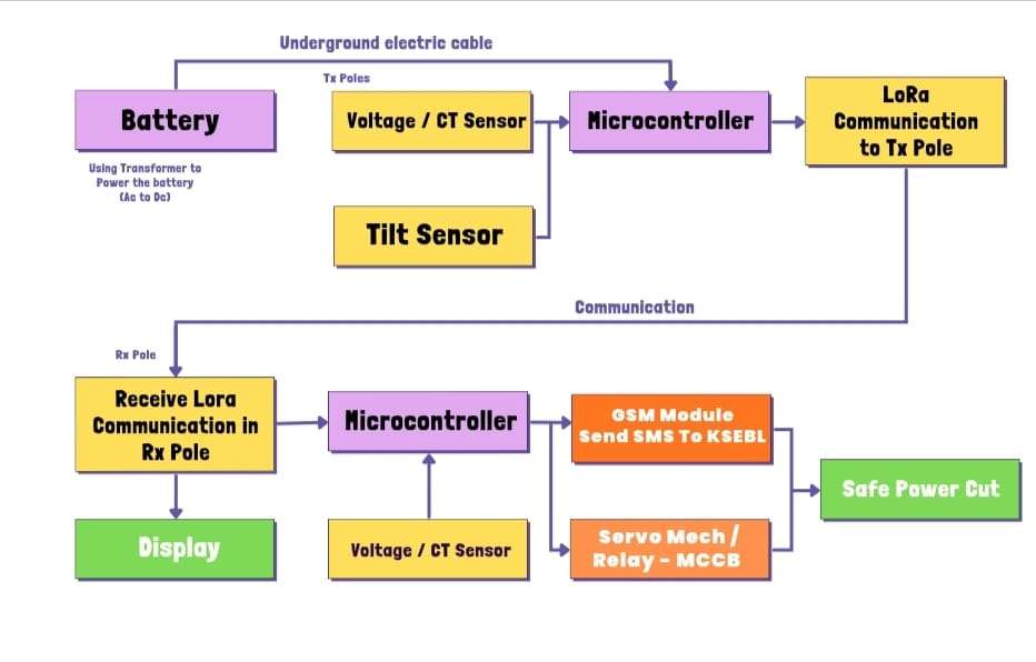
BLOCK DIAGRAM :
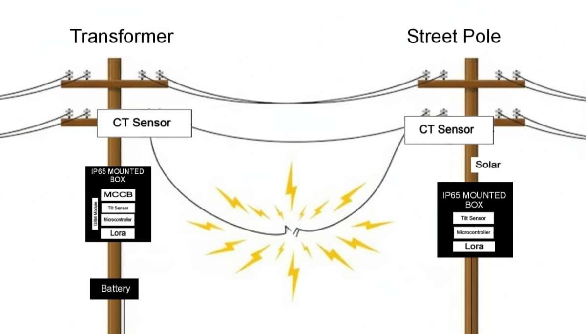
SAMPLE 2D DIAGRAM :
FINAL OUTPUT :
BoM Link :
https://www.digikey.in/short/dpjt3f5p
Some components models not available but I put another model components
PROJECT CONCEPT
Our project is a Smart Breakage Detection and Auto-Powercut System for local transmission lines. It continuously monitors the electrical pole using sensors such as tilt, voltage, and current sensors. If the pole falls or the line breaks, the system immediately detects the abnormal condition. Using ESP32 + Edge AI, it analyzes sensor data at the device level and sends fast alerts to the EB office using LoRa / GSM. At the same time, a servo-based mechanism cuts the power in that section to prevent accidents, fire hazards, and electrocution.
PROBLEM IN SOCIETY
In many areas, electric poles fall due to wind, accidents, or natural disasters. When a pole falls, the live wire may touch the ground or nearby houses. This causes:
High risk of electrocution to public
Chance of fire accidents
Long delays before EB staff identify the fault
Difficulty in locating the exact break point
Manual shutdown causes more damage and power loss
People often report only after the incident happens. No real-time detection exists in many rural and semi-urban areas.
SOLUTION
Our system provides a fully automated safety mechanism:
1. Tilt sensor detects pole movement or fall.
2. Voltage & current sensors detect wire break or abnormal flow.
3. ESP32 with Edge AI analyzes data locally for faster decision-making.
4. LoRa/GSM sends instant alert messages to the EB office with fault information.
5. Servo/MCCB mechanism cuts power automatically in the affected line.
6. Buzzer + LCD give local alerts to workers and nearby people.
7. System runs even during power issues using a lithium battery backup.
This ensures quick response, improved safety, and accurate detection without waiting for manual inspection.
ADVANTAGES
Immediate detection of pole fall or line break
Automatic power shutdown prevents electrocution & fire
Faster response through real-time SMS/LoRa alerts
Highly reliable because Edge AI processes data on-device
Low cost compared to traditional MCCB-based systems
Prevents accidents and increases public safety
Works in rural areas even with low network coverage
Accurate & continuous monitoring of field conditions
Easy to install and maintain
PROTOTYPE