PROJECT SUMMARY
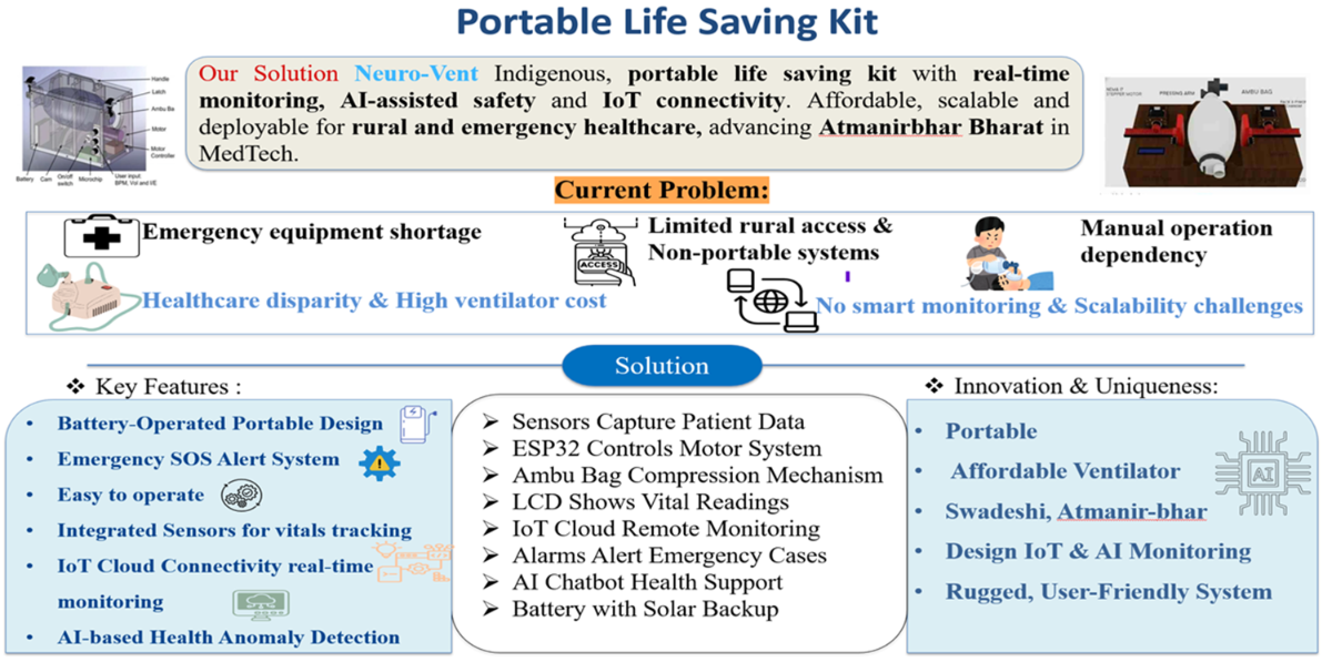
The Portable Life-Saving Kit is a compact, low-cost emergency medical support system designed to provide immediate respiratory assistance and vital sign monitoring during critical situations. The system integrates an automated ventilator mechanism with real-time monitoring of three essential vital parameters: SpO₂ (oxygen saturation), heart rate, and body temperature.
The kit is built using a microcontroller-based architecture ESP-32 to ensure reliable processing, portability, and optional wireless data transmission. It is specifically designed for use in ambulances, accident sites, rural healthcare centers, disaster zones, and home-care environments, where access to full ICU facilities is limited.
By combining ventilation support with continuous vital monitoring in a single portable unit, the project aims to stabilize patients during the critical “golden hour”, reducing mortality risk and improving emergency response efficiency. The system emphasizes affordability, ease of use, and rapid deployment, making it suitable for first responders, paramedics, and primary healthcare providers.
PROBLEM STATEMENT
SOLUTION
.png)
3.1 Working
The proposed system is designed for use during emergency situations, especially within the golden hour, where immediate respiratory support and vital monitoring are required. The methodology consists of the design and integration of an automated ventilation mechanism, vital parameter monitoring unit, pressure safety system, and portable power supply to ensure reliable operation in low‑resource environments.
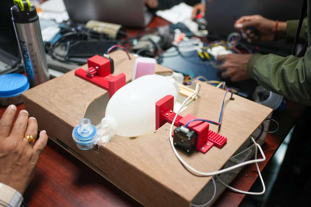
1.Automated Ventilation Mechanism
The ventilation support system is developed using a mechanical compression mechanism to automate the Ambu‑bag operation. A rack‑and‑pinion based linear actuation system driven by stepper motors is used to control the compression and release of the bag. The controller regulates the breathing cycle by adjusting tidal volume (VT), respiratory rate (RR), and inspiratory‑to‑expiratory (I:E) ratio. These parameters allow the system to provide controlled and repeatable ventilation suitable for emergency stabilization.
2. Vital Parameter Monitoring
To monitor the patient’s condition in real time, vital sensors are integrated into the system. The parameters measured include heart rate, oxygen saturation (SpO₂), and body temperature. The sensor data is processed using a microcontroller and displayed on a digital interface, allowing the operator to continuously observe the patient’s physiological status during operation. This monitoring helps in adjusting ventilation settings based on the patient response.
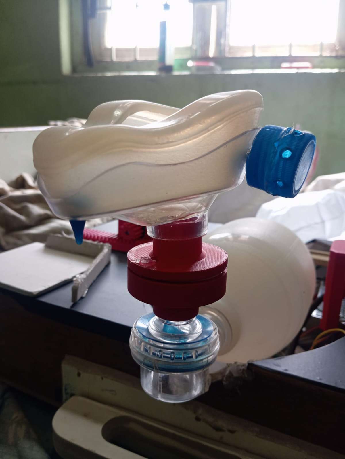
3. Airway Pressure Monitoring and Safety
A pressure sensing unit is incorporated to measure airway pressure during the ventilation cycle. The system maintains the pressure within the safe clinical range to prevent over‑inflation of the lungs. If the pressure exceeds the predefined limit, the controller stops the compression mechanism to ensure patient safety.
4. Portable Power and Solar Support
To ensure usability in ambulances, disaster zones, and rural healthcare environments, the system is powered using a rechargeable battery. A solar charging provision is included to allow operation in off‑grid conditions. This makes the device suitable for emergency deployment where continuous power supply may not be available.
5. System Integration
All modules, including the mechanical ventilator, vital monitoring sensors, pressure sensor, and power unit, are integrated into a compact portable structure. The complete system is designed to act as life saving kit that can provide temporary respiratory assistance and patient monitoring until advanced medical care becomes available.
.png)
Step 1: System Start and Power ON
When the system is powered ON, the controller initializes all connected modules including the ESP32 controller, sensors, motor driver, dashboard interface, and AI chatbot communication module. Default settings are loaded into the system memory.
Step 2: Parameter Setting
The operator sets the required ventilation parameters such as tidal volume (VT), respiratory rate (RR), and inspiratory‑to‑expiratory ratio (I:E).
These parameters are stored in the controller and used to control the ventilation cycle.
Step 3: Sensor Initialization and Data Reading
The system starts reading the vital sensors continuously.
The following parameters are measured:
- SpO₂ (oxygen saturation)
- Body temperature
- Airway pressure
The sensor values are sent to the controller for processing.
Step 4: Dashboard Display
The processed sensor data is transmitted to the dashboard.
The dashboard displays real‑time values of vital parameters and system status so that the operator can monitor the patient continuously.
Step 5: Motor Control Signal Generation
Based on the selected ventilation parameters, the controller sends control signals to the motor driver.The motor driver controls the stepper motor speed and direction.
Step 6: Rack and Pinion Mechanism Operation
The stepper motor drives the rack‑and‑pinion mechanism.
This mechanism converts rotary motion into linear motion to compress and release the Ambu bag.
Step 7: Ambu Bag Compression and Airflow
The Ambu bag is compressed according to the set VT, RR, and I:E ratio.
This produces controlled airflow which is delivered to the patient.
Step 8: Safety Check
During each cycle, the system checks the pressure sensor and vital parameters.
If the pressure or vital values exceed the safe limit, the controller stops the motor and generates an alert on the dashboard.
Step 9: Continuous Loop Operation
The system continues running in a loop:
- Read sensors
- Display data
- AI analysis
- Motor control
- Safety check
This process repeats until the system is turned OFF or the patient is shifted to advanced medical car.
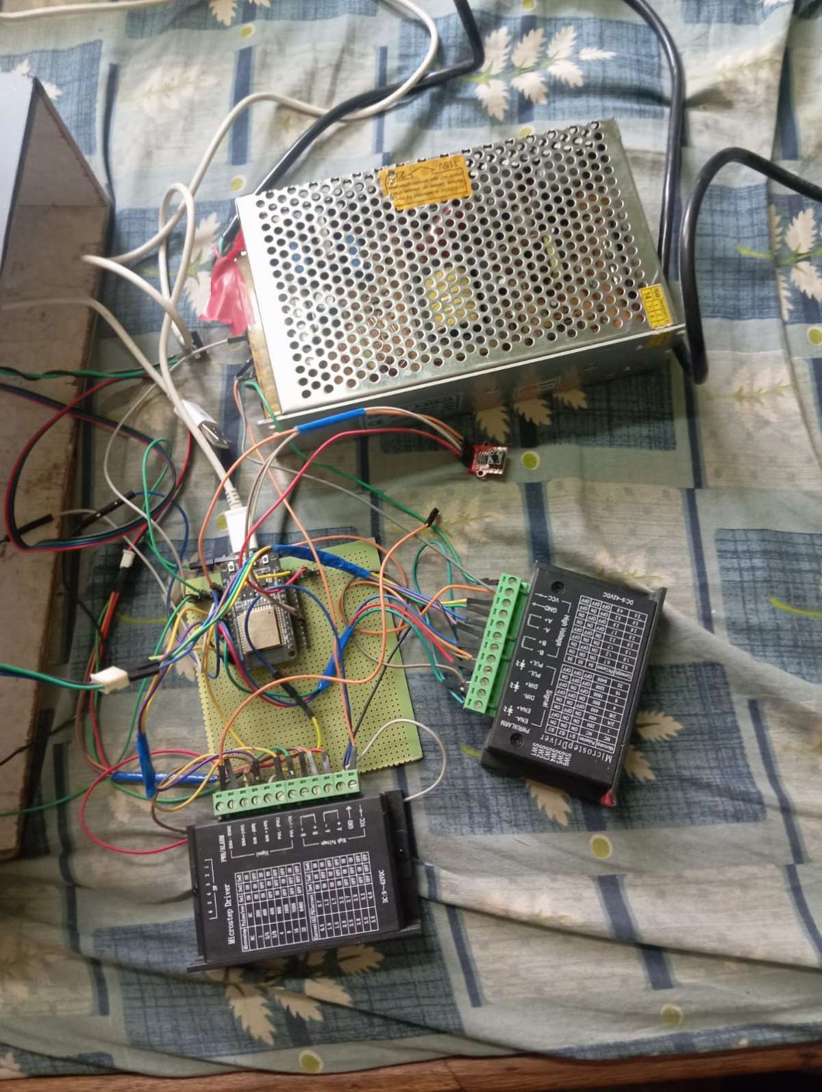
Implementation
circuit diagram for breathing support
.png)
codes
#include <Arduino.h>
#include <WiFi.h>
#include <WebServer.h>

// -------- WIFI --------
const char* WIFI_SSID = "Pj26";
const char* WIFI_PASS = "kumar@26";

WebServer server(80);

// -------- MOTOR PINS --------
#define PUL_A 18
#define DIR_A 19
#define ENA_A 21

#define PUL_B 22
#define DIR_B 23
#define ENA_B 5

// -------- SAFETY --------
#define SAFETY_PIN 4
#define BUZZER_PIN 15
#define EMERGENCY_BTN 27

// -------- PARAMETERS --------
float desired_tidal_ml = 450.0;
float RR = 12.0;
float IE_in = 1.0;
float IE_ex = 2.0;

bool running = false;

// -------- POSITION TRACKING --------
long currentPosition = 0;   // 🔥 KEY VARIABLE

// -------- TIMING --------
long steps_target = 600;
unsigned long delayMicros_in = 600;
unsigned long delayMicros_ex = 600;

// -------- BUZZER --------
bool buzzerActive = false;
unsigned long buzzerTimer = 0;

// -------- COMPUTE --------
void computeVentParams() {
  steps_target = map(desired_tidal_ml, 100, 500, 200, 1200);

  float period = 60.0 / RR;
  float inhale = period * (IE_in / (IE_in + IE_ex));
  float exhale = period - inhale;

  delayMicros_in = (inhale * 1000000) / (steps_target * 2);
  delayMicros_ex = (exhale * 1000000) / (steps_target * 2);

  if (delayMicros_in < 50) delayMicros_in = 50;
  if (delayMicros_ex < 50) delayMicros_ex = 50;
}

// -------- STEP --------
void stepBoth(unsigned long d) {
  digitalWrite(PUL_A, HIGH);
  digitalWrite(PUL_B, HIGH);
  delayMicroseconds(d);
  digitalWrite(PUL_A, LOW);
  digitalWrite(PUL_B, LOW);
  delayMicroseconds(d);
}

// -------- RETURN TO HOME (ACCURATE) --------
void returnToStart() {

  Serial.println("Returning to HOME...");

  digitalWrite(ENA_A, LOW);
  digitalWrite(ENA_B, LOW);

  if (currentPosition > 0) {

    digitalWrite(DIR_A, HIGH);
    digitalWrite(DIR_B, HIGH);

    while (currentPosition > 0) {
      stepBoth(delayMicros_ex);
      currentPosition--;
    }
  }

  digitalWrite(ENA_A, HIGH);
  digitalWrite(ENA_B, HIGH);

  running = false;

  Serial.println("HOME reached ✔");
}

// -------- BREATH --------
void doOneBreath() {

  // INHALE
  digitalWrite(DIR_A, LOW);
  digitalWrite(DIR_B, LOW);

  for (int i = 0; i < steps_target; i++) {
    if (!running) return;
    stepBoth(delayMicros_in);
    currentPosition++;   // 🔥 track forward
  }

  // EXHALE
  digitalWrite(DIR_A, HIGH);
  digitalWrite(DIR_B, HIGH);

  for (int i = 0; i < steps_target; i++) {
    if (!running) return;
    stepBoth(delayMicros_ex);
    currentPosition--;   // 🔥 track backward
  }
}

// -------- ROUTES --------
void handleStart() {
  computeVentParams();
  digitalWrite(ENA_A, LOW);
  digitalWrite(ENA_B, LOW);
  running = true;
  server.send(200, "text/plain", "STARTED");
}

void handleStop() {
  running = false;
  returnToStart();
  server.send(200, "text/plain", "STOPPED");
}

void handleSet() {
  if (server.hasArg("vt")) desired_tidal_ml = server.arg("vt").toFloat();
  if (server.hasArg("rr")) RR = server.arg("rr").toFloat();
  if (server.hasArg("ie_in")) IE_in = server.arg("ie_in").toFloat();
  if (server.hasArg("ie_ex")) IE_ex = server.arg("ie_ex").toFloat();

  computeVentParams();
  server.send(200, "text/plain", "UPDATED");
}

void handleEmergency() {
  desired_tidal_ml = 450;
  RR = 14;
  IE_in = 1;
  IE_ex = 2;

  computeVentParams();

  digitalWrite(ENA_A, LOW);
  digitalWrite(ENA_B, LOW);

  running = true;

  server.send(200, "text/plain", "EMERGENCY");
}

// -------- SETUP --------
void setup() {

  Serial.begin(115200);

  pinMode(PUL_A, OUTPUT);
  pinMode(DIR_A, OUTPUT);
  pinMode(ENA_A, OUTPUT);

  pinMode(PUL_B, OUTPUT);
  pinMode(DIR_B, OUTPUT);
  pinMode(ENA_B, OUTPUT);

  pinMode(SAFETY_PIN, INPUT_PULLUP);
  pinMode(EMERGENCY_BTN, INPUT_PULLUP);

  pinMode(BUZZER_PIN, OUTPUT);
  digitalWrite(BUZZER_PIN, LOW);

  digitalWrite(ENA_A, HIGH);
  digitalWrite(ENA_B, HIGH);

  WiFi.begin(WIFI_SSID, WIFI_PASS);

  while (WiFi.status() != WL_CONNECTED) {
    delay(500);
  }

  Serial.println("WiFi Connected");
  Serial.println(WiFi.localIP());

  server.on("/start", handleStart);
  server.on("/stop", handleStop);
  server.on("/set", handleSet);
  server.on("/emergency", handleEmergency);

  server.begin();
}

// -------- LOOP --------
void loop() {

  server.handleClient();

  // 🚨 SAFETY BUTTON
  if (digitalRead(SAFETY_PIN) == LOW) {

    Serial.println("🚨 SAFETY TRIGGER");

    running = false;

    // buzzer ON
    digitalWrite(BUZZER_PIN, HIGH);
    buzzerActive = true;
    buzzerTimer = millis();

    returnToStart();
  }

  // 🔘 HARDWARE EMERGENCY
  if (digitalRead(EMERGENCY_BTN) == LOW) {
    handleEmergency();
  }

  // 🔔 BUZZER OFF AFTER 1s
  if (buzzerActive && millis() - buzzerTimer > 1000) {
    digitalWrite(BUZZER_PIN, LOW);
    buzzerActive = false;
  }

  // RUN
  if (running) {
    doOneBreath();
  }
}
circuit diagram for vital parameter
.png)
.jpeg)
codes
#include <Wire.h>
#include "MAX30105.h"
#include <LiquidCrystal_I2C.h>
#include <Adafruit_MLX90614.h>

MAX30105 sensor;
LiquidCrystal_I2C lcd(0x27, 16, 2);
Adafruit_MLX90614 mlx;

// Filters
float spo2_filtered = 97;
float hr_filtered = 70;

// Time
unsigned long lastSecond = 0;
int hh = 14, mm = 58, ss = 0;

// HR detection
bool peakDetected = false;
unsigned long lastPeakTime = 0;

int detectHR(long ir)
{
    static long prevIR = 0;
    int threshold = 1500;
    int hr = -1;

    if ((ir - prevIR) > threshold && !peakDetected)
    {
        peakDetected = true;
        unsigned long now = millis();
        unsigned long diff = now - lastPeakTime;
        lastPeakTime = now;

        if (diff > 280 && diff < 1500)
            hr = 60000 / diff;
    }

    if ((prevIR - ir) > threshold)
        peakDetected = false;

    prevIR = ir;
    return hr;
}

// Time update
void updateTime() {
  if (millis() - lastSecond >= 1000) {
    lastSecond = millis();
    ss++;
    if (ss >= 60) { ss = 0; mm++; }
    if (mm >= 60) { mm = 0; hh++; }
    if (hh >= 24) hh = 0;
  }
}

String timeString() {
  char buf[6];
  sprintf(buf, "%02d:%02d", hh, mm);
  return String(buf);
}

// SETUP
void setup() {
  Serial.begin(115200);
  Wire.begin(21, 22);

  lcd.init();
  lcd.backlight();

  if (!sensor.begin(Wire)) {
    lcd.print("MAX30102 FAIL!");
    while (1);
  }

  sensor.setup();
  sensor.setPulseAmplitudeRed(0x2A);
  sensor.setPulseAmplitudeIR(0x2A);

  if (!mlx.begin()) {
    lcd.print("MLX FAIL!");
    while (1);
  }

  lcd.print("System Ready");
  delay(1000);
  lcd.clear();
}

// LOOP
void loop() {

  updateTime();

  long ir = sensor.getIR();
  long red = sensor.getRed();

  // No finger
  if (ir < 50000) {
    lcd.setCursor(0, 0);
    lcd.print("Place Finger     ");
    lcd.setCursor(0, 1);
    lcd.print(timeString());

    Serial.println("{\"hr\":0,\"spo2\":0,\"temp\":0}");
    delay(1000);
    return;
  }

  // SpO2
  float ratio = (float)red / (float)ir;

  float spo2 =
      (-1254.82 * ratio) +
      (1550.46 * ratio * ratio) +
      (-620.23 * ratio * ratio * ratio) +
      421.16;

  spo2 = constrain(spo2, 70, 100);
  spo2_filtered = 0.85 * spo2_filtered + 0.15 * spo2;

  // HR
  int hr_raw = detectHR(ir);
  if (hr_raw > 40 && hr_raw < 180)
    hr_filtered = 0.8 * hr_filtered + 0.2 * hr_raw;

  // Temp
  float tempC = mlx.readObjectTempC();

  // JSON OUTPUT
  String data = "{";
  data += "\"hr\":" + String((int)hr_filtered) + ",";
  data += "\"spo2\":" + String((int)spo2_filtered) + ",";
  data += "\"temp\":" + String(tempC, 1);
  data += "}";

  Serial.println(data);

  // LCD
  lcd.setCursor(0, 0);
  lcd.print("SpO2:");
  lcd.print((int)spo2_filtered);
  lcd.print("% HR:");
  lcd.print((int)hr_filtered);

  lcd.setCursor(0, 1);
  lcd.print("T:");
  lcd.print(tempC, 1);
  lcd.print(" ");
  lcd.print(timeString());

  delay(500);
}
Working
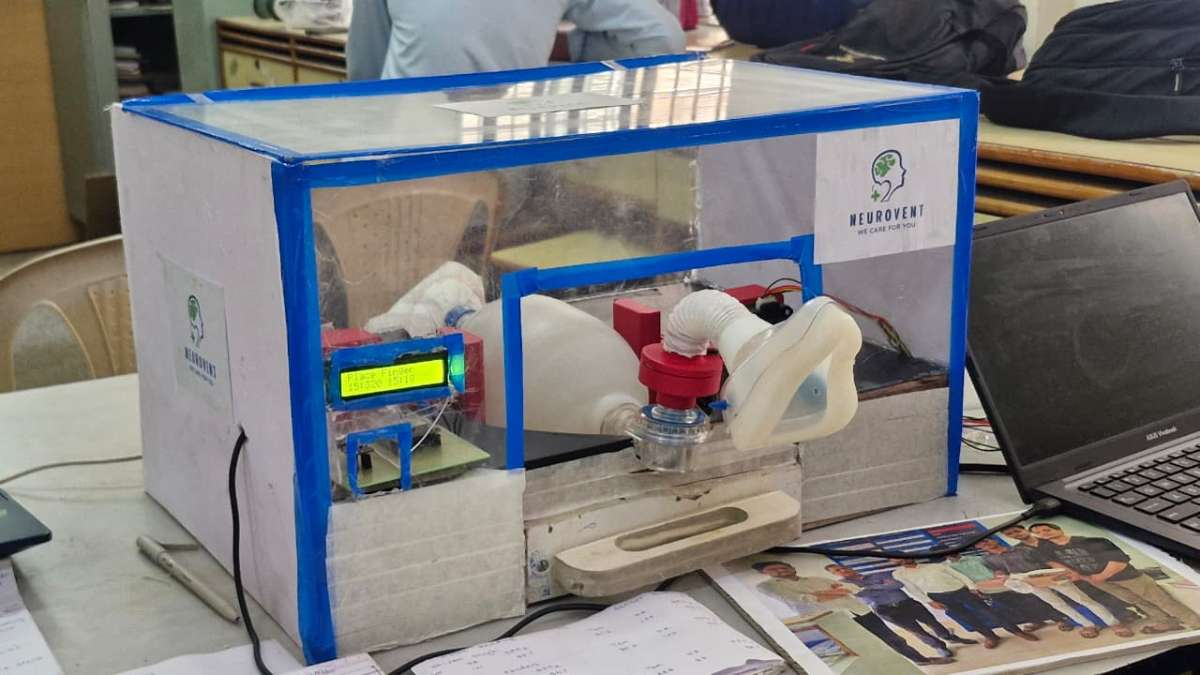
Final lookout
Observation
Ambu Bag Volume Range by Age Group
| Category | Weight Range (kg) | Bag Capacity | Typical Deliverable Tidal Volume | Use |
| Adult (including Aged / Elderly) | 50–100 kg | 1600–2000 mL | 400–600 mL | Normal adult ventilation, elderly patients |
| Aged | 40–60 kg | 1600–2000 mL | 350–500 mL | Elderly patients up to 60 kg |
| Child | 5–20 kg | 500–1000 mL | 150–400 mL | Children (approx.) |
| Infant | 2–10 kg | 250–500 mL | 30–80 mL | Babies up to 10 kg |
| Neonatal | 1–3 kg | 150–250 mL | 10–30 mL | Newborn babies |
Ventilation Parameters for Motor Rotation Mechanism
| S.No | Tidal Volume (mL) | RR (Breaths/min) | I:E Ratio | Motor Step |
| 1 | 450 | 12 | 1:2 | 9 |
| 2 | 400 | 15 | 1:2 | 8 |
| 3 | 350 | 13 | 1:2 | 7 |
Comparison of Measured Vital Parameters with Normal Range
| Name | Temperature (°C) | Normal Temp (°C) | Heart Rate (BPM) | Normal HR (BPM) | SpO₂ (%) | Normal SpO₂ (%) |
| Shivam Singh | 31.3 | 30–37 | 101 | 60–100 | 96 | 95–100 |
| Ayush Pandey | 30.3 | 30–37 | 104 | 60–100 | 94 | 95–100 |
| Pradip Kumar | 29.4 | 30–37 | 103 | 60–100 | 88 | 95–100 |
Sample 4
| 31.6 | 30–37 | 106 | 60–100 | 94 | 95–100 |
Sample 5
| 30.6 | 30–37 | 100 | 60–100 | 96 | 95–100 |
Sample 6
| 29.8 | 30–37 | 87 | 60–100 | 95 | 95–100 |
5.4 Competitors
| Solution / Competitor Type | Examples (Reference) | Cost | Portability | Skilled Operator Needed | Ventilation Control (VT, RR, I:E) | Safety (Pressure + Alarms) | Vital Monitoring (SpO₂, HR, Temp) | IoT / Dashboard |
| ICU Ventilator (Hospital Grade) | Dräger / GE / Philips | Very High | Low | Yes | High Precision | Yes (Advanced) | Separate monitor required | Limited |
| Transport Ventilator (Ambulance Type) | ResMed / Hamilton / Medtronic | High | Medium–High | Yes | Moderate | Partial | Limited | Minimal |
| Manual Ambu Bag Ventilation | Ambu Bag BVM | Very Low | Very High | Yes (Manual skill) | No | No | No | No |
| Basic Ambu Bag Automation Prototype | DIY Research models | Low | High | No/Minimal | Partial | Weak / Not reliable | No | No |
| Our Portable Life-Saving Kit | Neurovent | Low | High | No (Easy Use) | Yes (Controlled) | Yes (Smart Alerts)
| Yes (Integrated) | Yes (Live Dashboard + IoT) |
Conclusion
The implementation of the Portable Life-Saving Kit represents a significant advancement in emergency healthcare delivery, particularly in resource-limited and time-critical environments. Through careful design and development, the system demonstrates its ability to provide rapid diagnosis, continuous monitoring, and timely emergency response in situations where conventional medical infrastructure may be unavailable or inaccessible.
The project objectives were successfully achieved through the integration of vital sign monitoring sensors, an intelligent control unit, and an automated ventilation mechanism based on the Ambu bag. By continuously monitoring critical parameters such as heart rate, oxygen saturation, body temperature, and respiratory status, the system enables early detection of medical emergencies and supports informed clinical decision-making. The incorporation of IoT and AI technologies further enhances system functionality by allowing real-time data transmission, remote monitoring, and alert generation.
One of the key outcomes of the project is its potential to improve patient safety and survival rates while maintaining affordability and portability. Compared to conventional ICU-grade ventilators and diagnostic systems, the proposed solution offers a cost-effective alternative suitable for ambulances, rural healthcare centers, disaster response units, and public emergency setups. Additionally, the system’s safety features, including controlled ventilation parameters and alarm mechanisms, ensure reliable and consistent respiratory support.
Overall, the portable life-saving kit highlights the importance of innovative, intelligent, and accessible healthcare solutions in addressing modern medical challenges. By reducing response time, improving diagnostic accuracy, and extending emergency care to underserved areas, the proposed system contributes to strengthening healthcare preparedness and building a more resilient and inclusive healthcare ecosystem.
TARGET AUDIENCE
.png)
- Emergency Medical Technicians (EMTs) & Ambulance Staff – for providing immediate life support during patient transport
- Paramedics & First Responders – for rapid intervention at accident sites, disaster zones, or remote areas
- Rural & Primary Healthcare Centers (PHCs) – where advanced ICU equipment is unavailable
- Doctors & Nurses in Emergency Departments – as a quick stabilization support system
- Disaster Response Teams (NDRF/SDRF, NGOs) – for mass casualty management
- Military & Defense Medical Units – for field-level emergency care
- Home-care Providers – for patients requiring continuous monitoring and emergency support
- Mobile Health Units & Medical Camps – for temporary healthcare setups
Conclusion
.png)
.png)
Research and Reference
.png)
.png)
we are in contact with some doctor as shown above in the picture.
complete project
Thank you!!!!!!