
HELLO EVERYONE !!
I'm excited to share this project with you. Today, I'm documenting a system that's actively protecting my family.
This isn't a polished corporate product or a perfectly planned research project. It's a real story of late nights, burnt fingers from soldering irons, failed 3D prints, and that incredible moment when everything finally clicked together at 2 AM. SafeGuard was born from genuine fear after witnessing my neighbor's kitchen fire, built under intense time pressure, and refined through real-world testing in my own home.
Let's dive into how a project became a potentially life-saving device that my mother now trusts more than her own memory. Welcome to the SafeGuard story.
My Digikey List (BOM)
Click on Any Product To Open List
.png)
.png)
.png)
Why I Built This
Three months ago, my neighbour's kitchen caught fire. A slow LPG leak during the night, an early morning spark from the refrigerator compressor, and suddenly their home was engulfed in flames. They escaped, thankfully, but the incident shook our entire apartment building.
Most LPG accidents happen because we can't see or smell small leaks until it's too late. We trust a manual regulator knob and our own memory to turn off the gas before sleeping.
I realized I had the skills to build something better. Something that could detect leaks instantly, cut off gas supply automatically, and alert families before disaster strikes. The idea consumed me. I sketched designs during lectures, calculated load cell placements at midnight, and did some research.
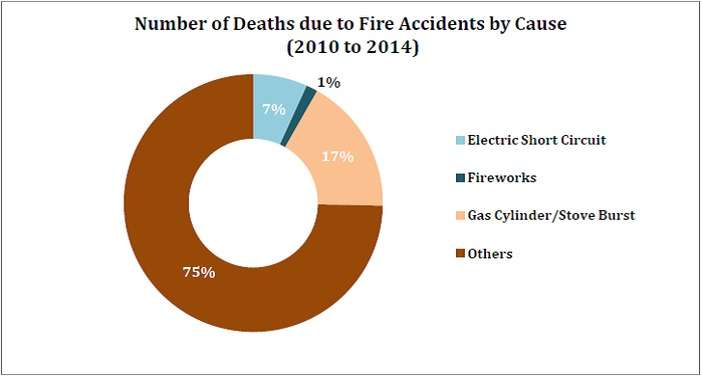
The Problem Statement
Every year, thousands of homes experience LPG-related accidents. In India alone, over Thousands of LPG cylinder explosions are reported annually, with countless more unreported incidents. The numbers are staggering, but behind each statistic is a family, a home, a life changed forever.
.png)
Gas leaks are invisible killers. LPG is heavier than air, so it settles at floor level where children and pets play. By the time you smell the odorant added to LPG, the concentration might already be dangerous. A single spark—from a light switch, a phone charger, static electricity can trigger catastrophe.
The Solution: SafeGuard Overview
SafeGuard transforms your ordinary LPG regulator into an intelligent safety system. At its core is an ESP32-C6 microcontroller that constantly monitors three critical parameters: gas leak presence, cylinder weight, Valve Status and time of day.
The MQ-2 sensor continuously samples the air around your cylinder, detecting even minor LPG concentrations. When it senses danger, the system reacts in under two seconds a servo motor physically turns the regulator valve to the off position, cutting the gas supply completely. Simultaneously, a buzzer sounds an alarm, and your phone receives an instant notification, even if you're away from home.
Four load cells positioned beneath the cylinder provide precise weight measurements, calculating exactly how much gas remains. You'll know whether you have enough gas for the week or if you need to order a refill soon. No more surprises in the middle of cooking.
The nighttime auto-shutoff feature adds an extra layer of protection. During sleeping hours, SafeGuard automatically closes the valve, ensuring that even if there's a leak or regulator failure, your family sleeps safely. You can override this manually through the app if needed.
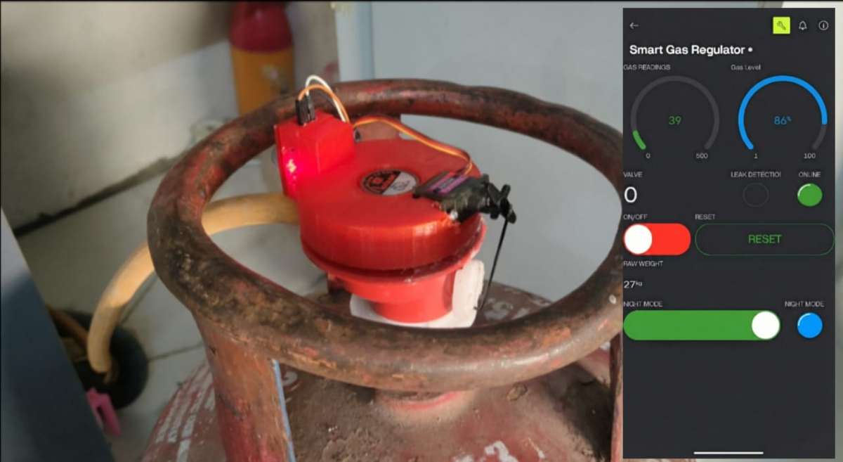
Everything connects to your smartphone via Blynk. Check gas levels from your bedroom Or anywhere around the world. Turn off the supply remotely if you forgot before leaving for vacation. Get alerts about unusual consumption patterns. The power of complete control, in your pocket.
Core features
Automatic Leak Protection MQ-2 sensor detects LPG presence and triggers instant valve shutoff with alarm and phone notification
Real-Time Gas Level Monitoring Four load cells measure cylinder weight and calculate remaining gas percentage with accuracy
Smart Night Mode Automatic gas supply cutoff during sleeping hours for enhanced safety
Complete Mobile Control Blynk app integration for remote monitoring, manual valve control, and instant alerts
Emergency Response System Multi-layer alert system: buzzer alarm, LED indicator, and push notifications
Fail-Safe Design Servo-controlled mechanical valve ensures gas can be cut off even during sensor failures
Low Gas Alerts Proactive notifications when cylinder reaches preset low levels, preventing unexpected outages
Universal Compatibility 3D-printed servo mount fits standard LPG regulators without permanent modifications
How SafeGuard Works: Complete Flow
SafeGuard's architecture revolves around the ESP32-C6 microcontroller as the brain of the system. The MQ-2 gas sensor continuously feeds analog data to the ESP32's ADC pin, while the HX711 amplifier processes signals from four load cells and communicates digitally. The ESP32 processes this information and controls outputs: the servo motor for valve actuation, buzzer for local alarms, and the onboard LED for status indication. WiFi connectivity links everything to the Blynk cloud platform, enabling remote monitoring and control.
All components share a common 5V power rail from a 2.1A power bank, with the ESP32-C6 regulating its own 3.3V logic internally. The system operates in a continuous loop—monitoring, analyzing, and responding to changes in gas concentration, cylinder weight, and user commands from the mobile app.
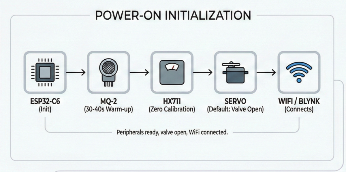
Power-On Initialization: When SafeGuard boots up, the ESP32-C6 initializes all peripherals. The MQ-2 sensor provides usable readings after just 30-40 Seconds of warm-up. The HX711 performs a zero calibration, and the servo -moves to its default position (gas valve open). WiFi connects to your home network, and the Blynk app establishes communication.
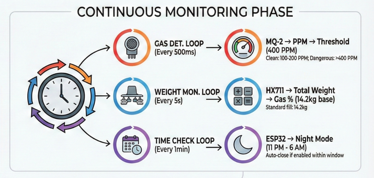
Continuous Monitoring Phase: Three parallel monitoring loops run simultaneously:
- Gas Detection Loop (every 500ms): The ESP32 reads the analog voltage from MQ-2's A0 pin, converts it to PPM (parts per million), and compares it against the 400 PPM threshold. Clean air reads around 100-200 PPM, while dangerous LPG concentrations push values above 400 PPM.
- Weight Monitoring Loop (every 5 seconds): The HX711 reads the combined signal from all four load cells, applies the calibration factor, and calculates total weight. Subtracting the empty cylinder weight (typically 15kg) gives the remaining gas weight. This converts to a percentage based on the standard 14.2kg fill.
- Time Check Loop (every minute): The ESP32 checks the current time against the night mode schedule (11 PM - 6 AM). If enabled via the app and within this window, the system automatically closes the valve.
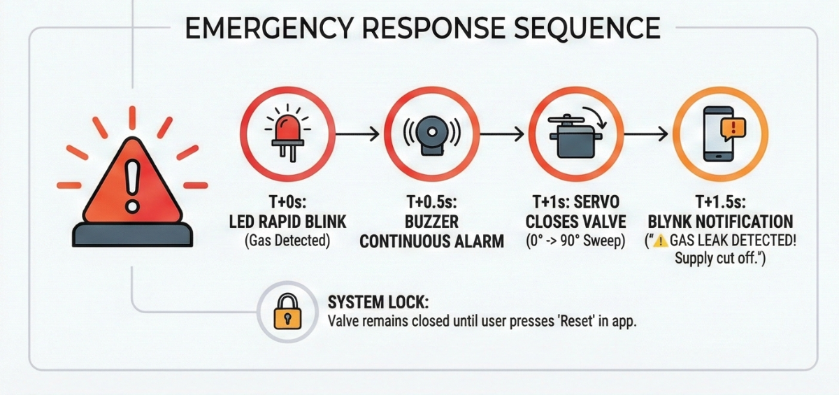
Emergency Response Sequence: When MQ-2 detects PPM levels above 400:
- T+0 seconds: Gas detected, onboard LED starts rapid blinking
- T+0.5 seconds: Buzzer activates with continuous alarm tone
- T+1 second: Servo rotates to close valve position (0° to 90° sweep)
- T+1.5 seconds: Blynk notification sent: " GAS LEAK DETECTED! Supply cut off."
- System locks: Valve remains closed until user presses "Reset" button in app
Normal Operation: Under safe conditions, the app displays real-time gas percentage, current PPM reading, and valve status. Users can manually open/close the valve, toggle night mode, and adjust settings. Low gas alerts trigger automatically when levels drop below 10% (approximately 1.4kg remaining).
Safety Logic Flowchart
.png)
Rapid Prototyping & Preparation
I cleared my entire workbench. Electronics assembly demands organization—one misplaced wire or lost screw can derail hours of work.
Test Each Component before moving to the project with Example sketches to Avoid Unnecessary troubleshooting and Time waste Between the build.
Lighting matters more than you'd think. I positioned a desk light directly over the work area. PCB soldering requires seeing those tiny solder joints clearly, and shadows cause mistakes. If you wear glasses, clean them—seriously, it helps.
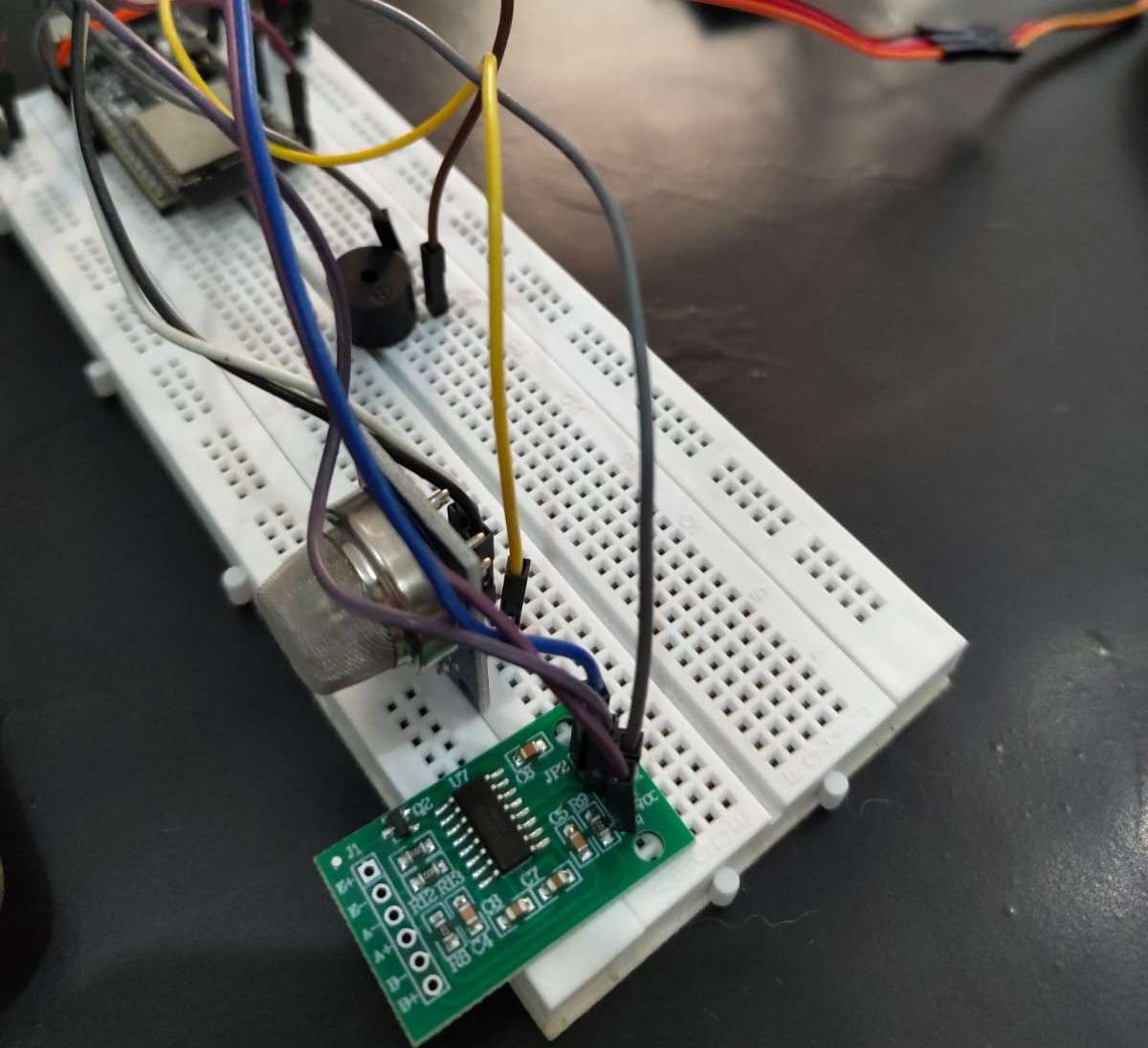
Before soldering anything permanent, I built the entire circuit on a breadboard. This let me test code and fix bugs without worrying about desoldering mistakes.
Build Process:
The build process spanned intense 3 days. I spent every available hour soldering, testing, troubleshooting, and refining. This wasn't a smooth linear process it was messy, frustrating, and deeply rewarding. I made mistakes, burned my fingers on the soldering iron twice, and nearly gave up when the load cells refused to calibrate properly on day three. But each obstacle taught me something valuable about electronics, mechanical design, and problem-solving under pressure.
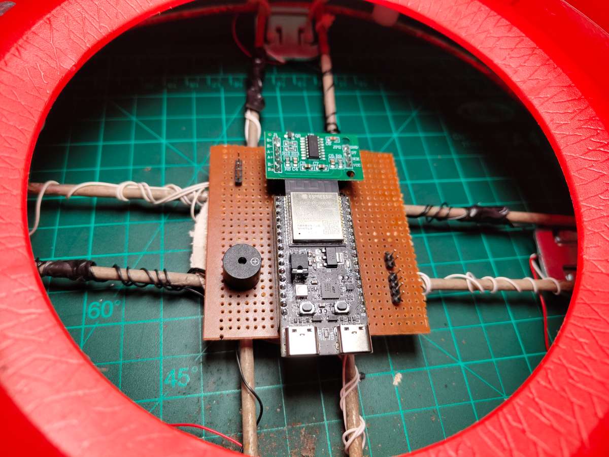
Circuit Schematic Diagram

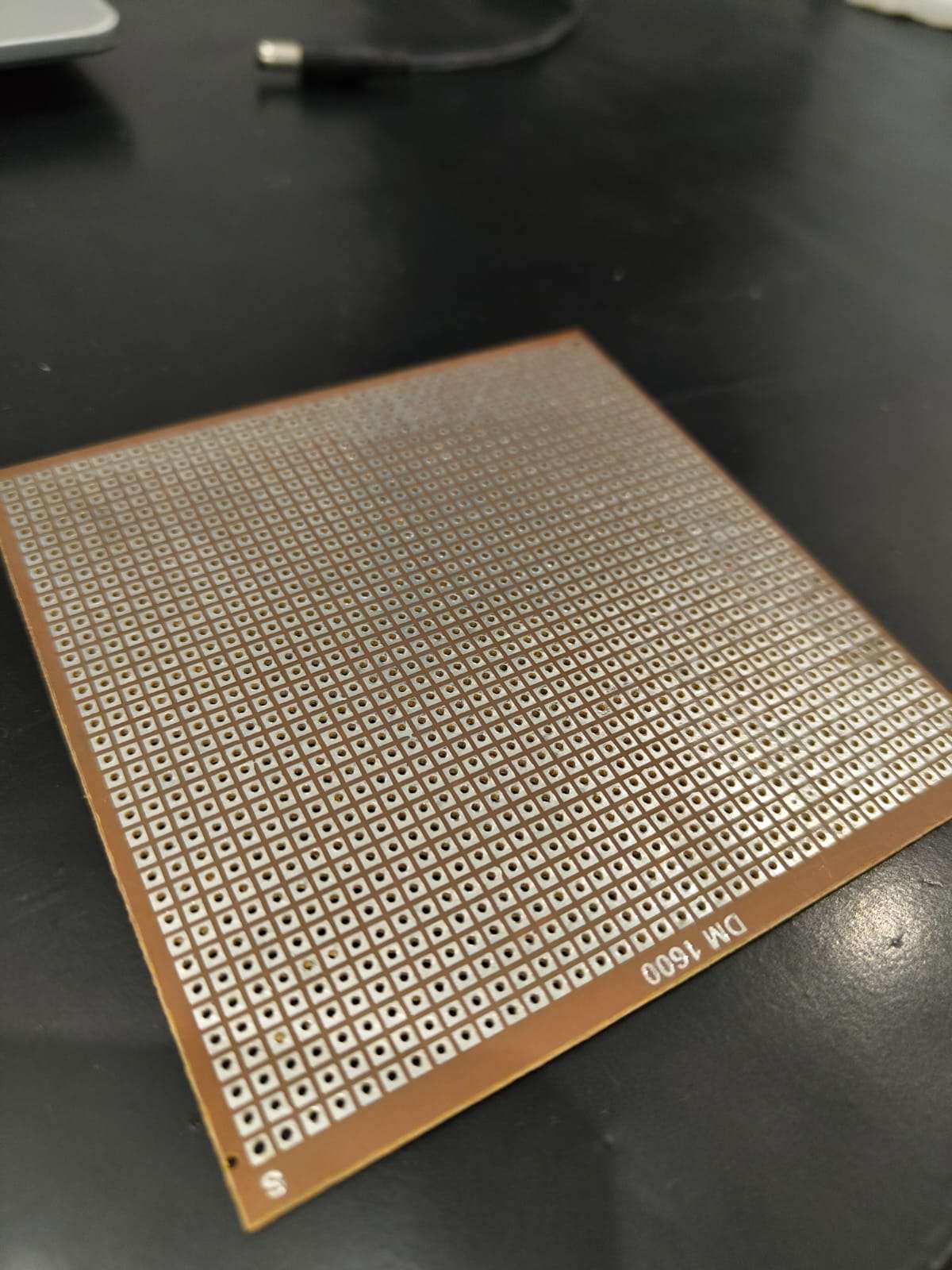
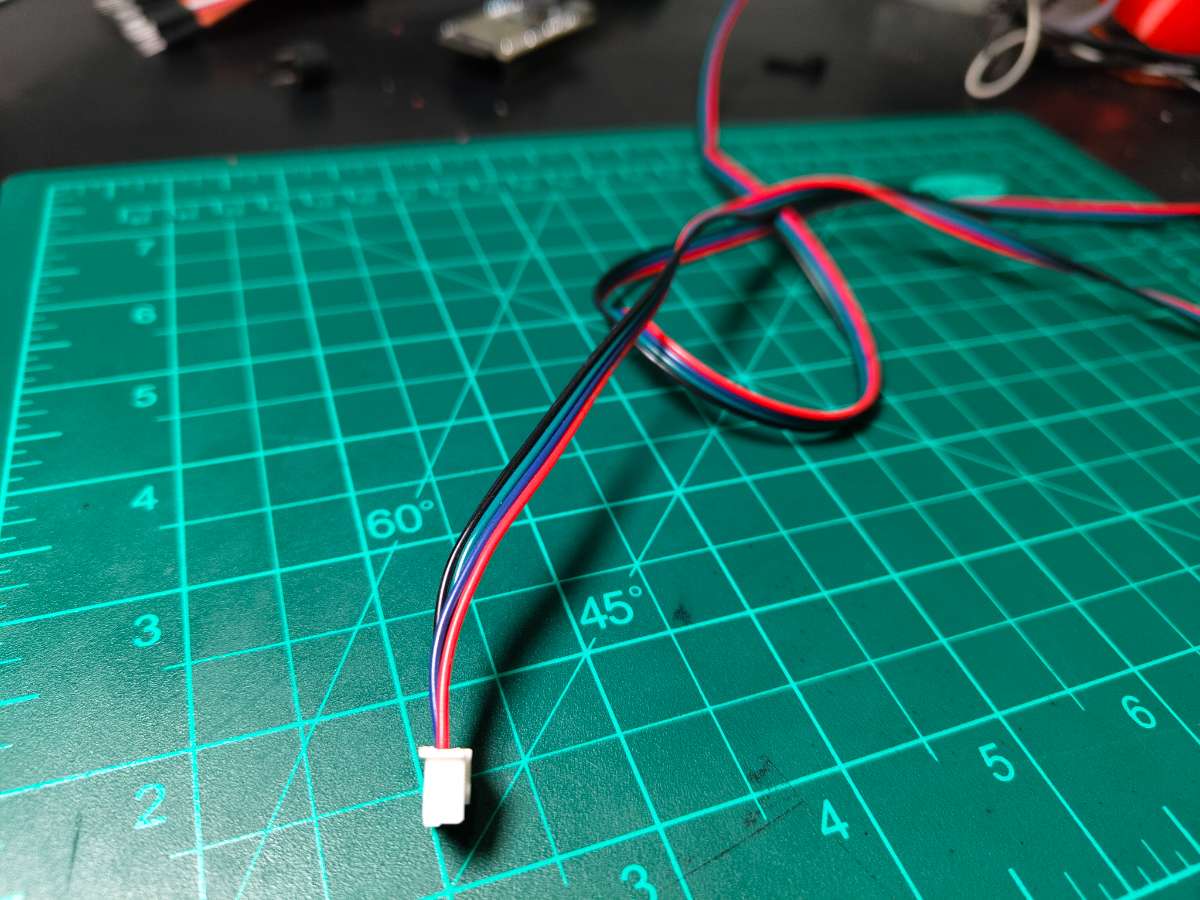
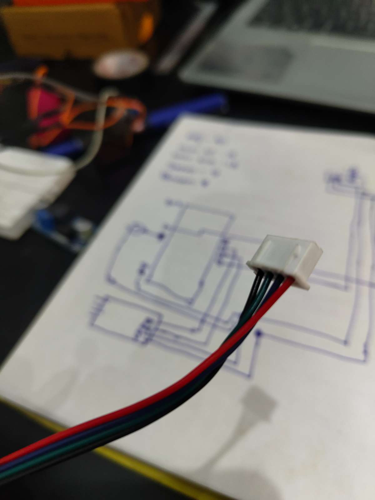
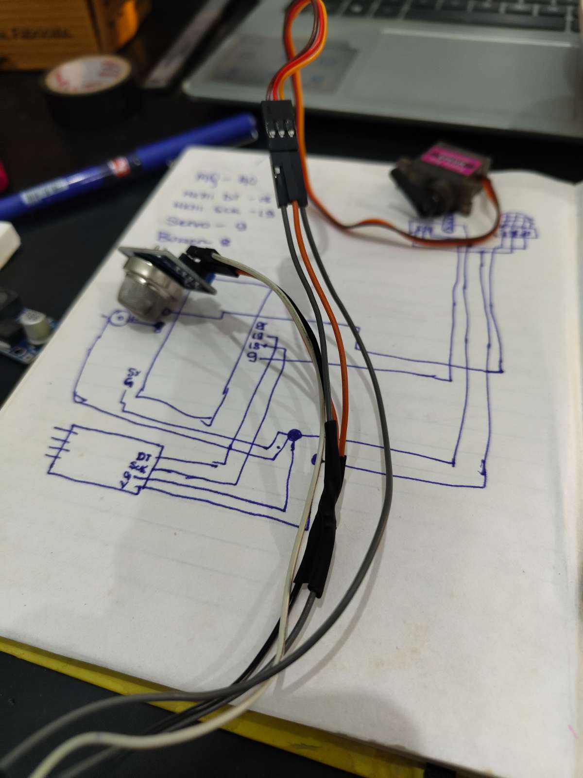
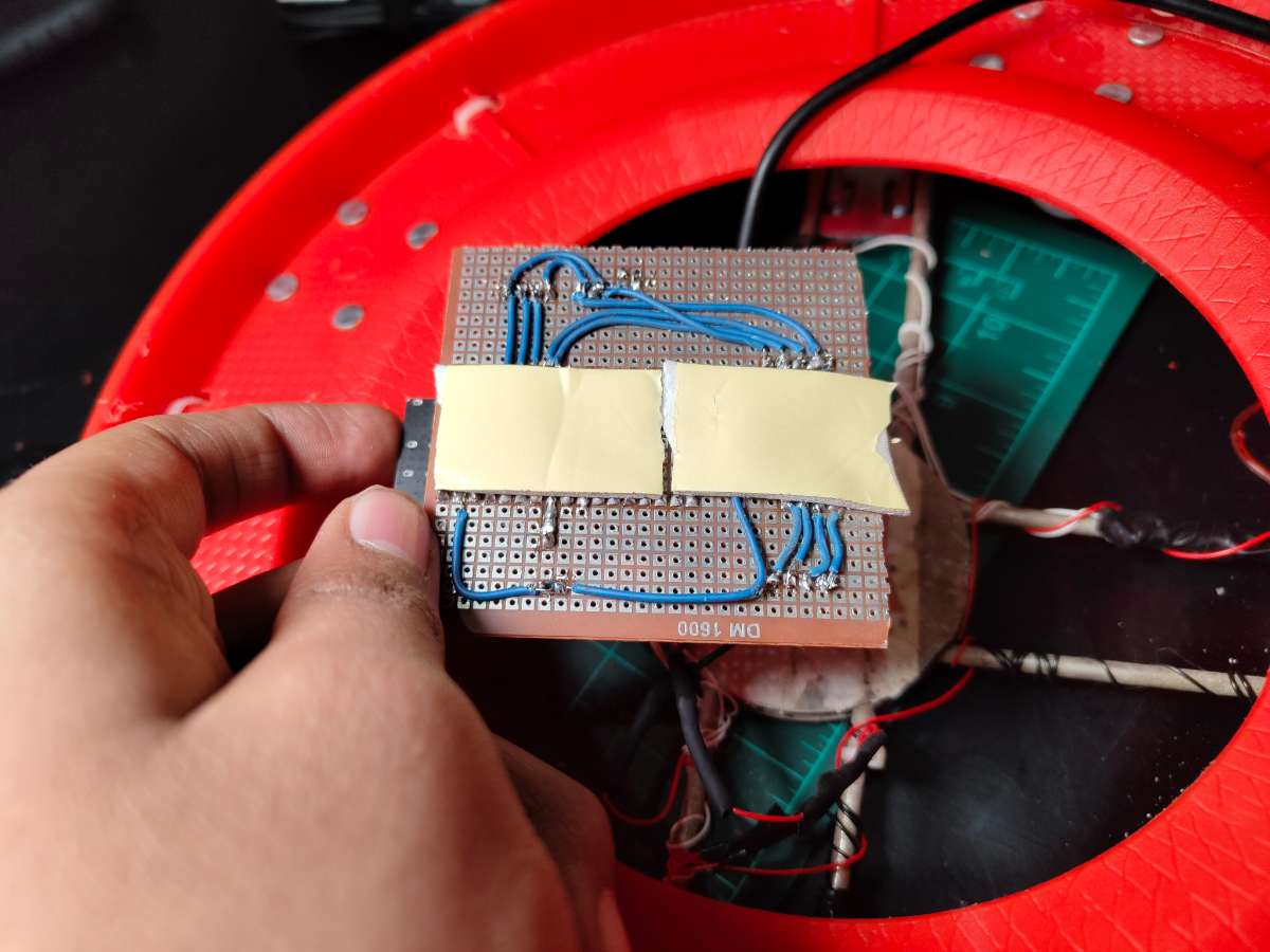
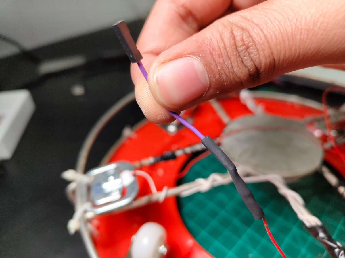
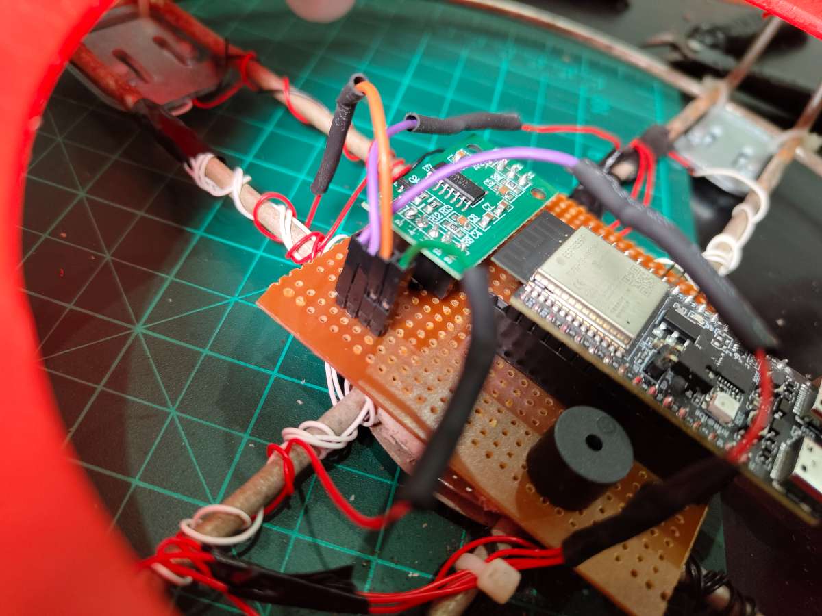
The circuit design centers on simplicity and reliability. Since I was racing against the project deadline, I hand-soldered everything on a zero PCB. I mounted male Berg strip connectors on the PCB for the MQ-2 sensor and servo—these components live on top of the regulator, so I needed a detachable cable connection. I repurposed a stepper motor cable for this, which had the perfect wire gauge and length.


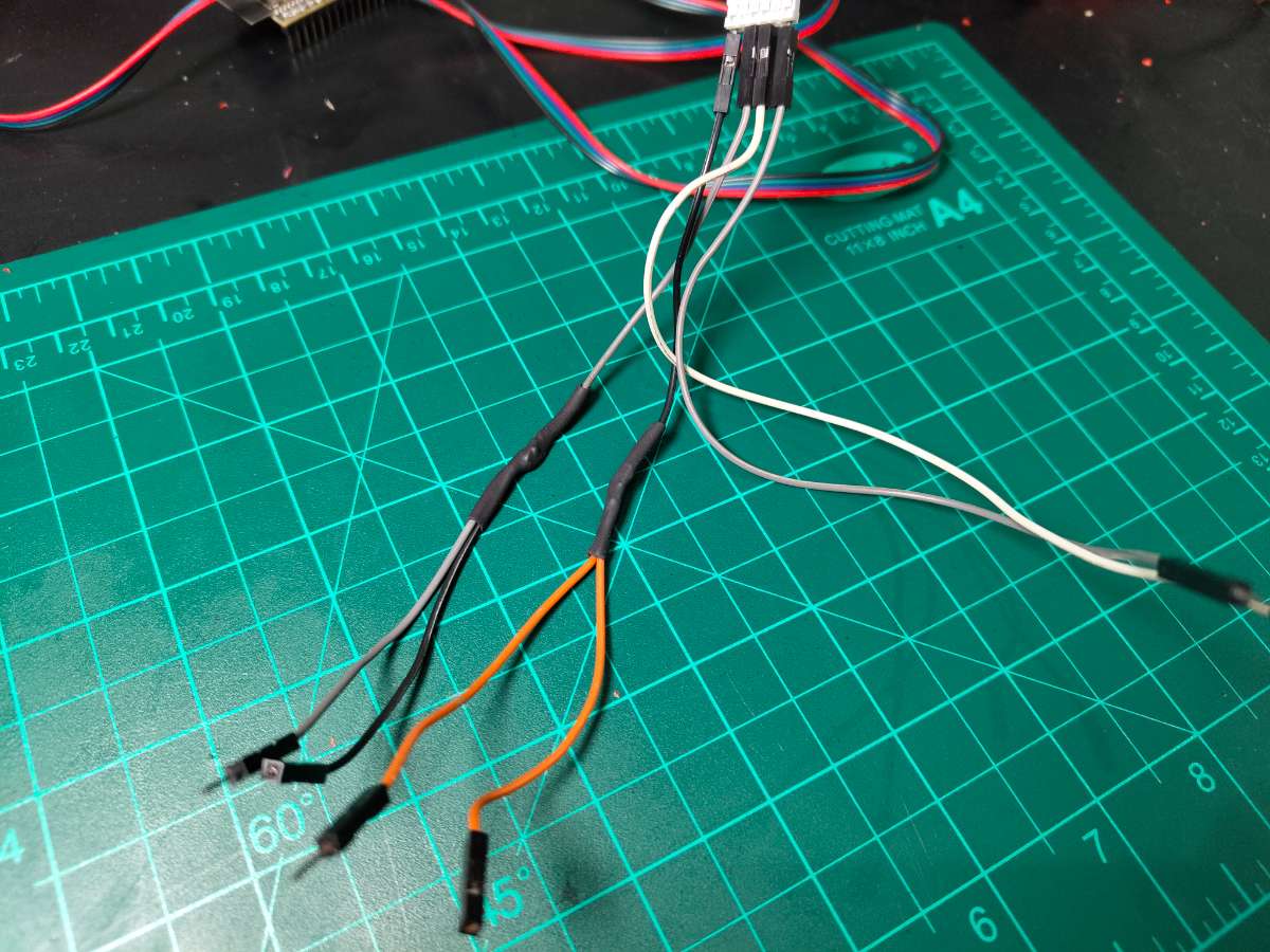
Connectivity from top Mount To Base
I'm using Stepper motor Cable TO connect the regulator mount with the microcontroller in the base. I Created Simple PNP Mechanism For Better Prototyping and Ease of use
Key Design Decisions:
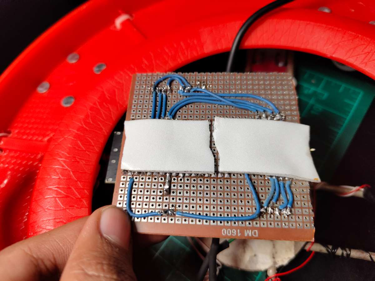
- Common Ground: All grounds tie to a thick copper bus I soldered along the PCB edge
- 5V Distribution: Another copper bus carries 5V to all components
- Signal Isolation: Kept MQ-2 analog traces away from servo PWM wire to minimize noise
- Strain Relief: Used hot glue on Berg strip connections to prevent cable stress damage
Power Distribution: The 5V power bank connects directly to the common power bus. The ESP32-C6 has an onboard 3.3V regulator that powers its internal logic. The MQ-2 sensor module has its own onboard regulator, so it safely accepts 5V input. The servo and buzzer run directly on 5V.
Important Note on Servo Power: I'm powering the servo directly from the same 5V rail as the ESP32. This works with my 2.1A power bank, but during servo rotation, there can be voltage dips that might cause the ESP32 to brown out or reset. I strongly recommend adding a 1000µF electrolytic capacitor across the servo's power pins (positive to 5V, negative to GND) to smooth these current spikes. I didn't add one due to time constraints, but it's a best practice for servo-based projects.
ESP32-C6 Pin Mapping
| Component | ESP32-C6 Pin | Pin Function | Notes |
|---|---|---|---|
| Servo Motor | GPIO 9 | PWM Output | Controls valve position (0-90°) |
| HX711 DT | GPIO 18 | Data Input | Serial data from load cell amplifier |
| HX711 SCK | GPIO 19 | Clock Output | Clock signal for HX711 communication |
| Buzzer | GPIO 8 | Digital Output | HIGH = buzzer on, LOW = off |
| MQ-2 Sensor | ADC0 (A0) | Analog Input | Reads gas concentration (0-4095) |
| Onboard LED | GPIO (built-in) | Digital Output | Status indicator |
| 5V Input | 5V Pin | Power | From power bank |
| Ground | GND | Ground | Common ground with all components |

MQ-2 Connections
| MQ-2 Module Pin | Wire Color | Connects To | Function |
|---|---|---|---|
| VCC | Red | 5V Rail | Power supply |
| GND | Black | Common GND | Ground reference |
| A0 | Yellow/Green | ESP32 ADC0 | Analog gas reading |
| D0 | - | Not Connected | Digital output not used |
The MQ-2 module mounts on the 3D-printed servo assembly near the regulator, so it's positioned close to the potential leak source. The cable running from the PCB to the sensor should be kept under 1 meter to minimize analog signal degradation.
Servo Motor Connections
| Servo Wire Color | Connects To | Function |
|---|---|---|
| Brown/Black | Common GND | Ground |
| Red | 5V Rail | Power (peak 500mA) |
| Orange/Yellow | ESP32 GPIO 9 | PWM control signal |
Mounting Configuration: The servo attaches to a 3D-printed bracket that clamps around the existing regulator body. The servo horn connects to the knob using a custom-printed coupling. When the servo rotates from 0° to 90°, it physically turns the regulator knob from fully open to fully closed. I designed the mount to be non-permanent you can remove it and return the regulator to normal manual operation anytime.
Load Cells + HX711 Connections
| Connection Point | Load Cell Wires | HX711 Terminal |
|---|---|---|
| E+ (Excitation +) | TL Red | E+ |
| E- (Excitation -) | BR Red | E- |
| A+ (Signal +) | TR Red | A+ |
| A- (Signal -) | BL Red | A- |
Internal Load Cell Bridges:
- TL White ↔ TR White (bridge link)
- TL Black ↔ BL Black (bridge link)
- TR Black ↔ BR Black (bridge link)
- BL White ↔ BR White (bridge link)
.jpg)
HX711 to ESP32:
| HX711 Pin | Wire Color | ESP32-C6 Pin |
|---|---|---|
| VCC | Red | 5V Rail |
| GND | Black | Common GND |
| DT (Data) | Green | GPIO 18 |
| SCK (Clock) | Yellow | GPIO 19 |
The HX711 is a 24-bit ADC specifically designed for load cell amplification. It communicates with the ESP32 using a simple two-wire protocol—one clock line and one data line. The HX711_ADC library for Arduino handles all the communication complexity.
Buzzer & LED Connections
| Buzzer Terminal | Connects To |
|---|---|
| Positive (+) | ESP32 GPIO 8 |
| Negative (-) | Common GND |
I used an active buzzer (has internal oscillator), so it produces a tone when GPIO 8 goes HIGH. For passive buzzers, you'd need to generate a PWM tone. The active type is simpler and loud enough for kitchen environments.
Onboard LED: The ESP32-C6 has a built-in LED connected to an internal GPIO (usually GPIO 15, but varies by manufacturer). This LED blinks slowly during normal operation, rapidly during gas detection, and stays off when the system is in night mode.
Power Supply Design
Let me break down the power consumption of each component to ensure the 2.1A (10.5W) power bank provides adequate current:
Component Power Draw:
| Component | Operating Voltage | Typical Current | Peak Current | Power Consumption |
|---|---|---|---|---|
| ESP32-C6 (WiFi active) | 3.3V (from 5V) | 120mA | 250mA | 0.4W - 0.8W |
| MQ-2 Sensor Module | 5V | 150mA | 180mA | 0.75W - 0.9W |
| MG90s Servo (idle) | 5V | 10mA | - | 0.05W |
| SG90 Servo (rotating) | 5V | - | 500mA | 2.5W |
| HX711 + Load Cells | 5V | 15mA | 20mA | 0.075W - 0.1W |
| Active Buzzer | 5V | 30mA | 30mA | 0.15W |
| Onboard LED | 3.3V | 5mA | 5mA | 0.017W |
Total Power Analysis:
- Normal Operation (servo idle, buzzer off): 120 + 150 + 10 + 15 + 5 = 300mA (1.5W)
- Peak Load (servo rotating, buzzer active): 250 + 180 + 500 + 20 + 30 + 5 = 985mA (4.9W)
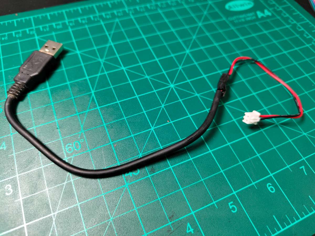
DIY Power Cable for Powerbank.The 2.1A power bank provides more than double the peak current requirement, giving us a healthy safety margin. This headroom is important because power banks often can't sustain their rated current continuously, and we want to avoid voltage droops during servo operation.
5V Regulation Circuit
Since I'm using a 5V power bank directly, no additional voltage regulation is needed. The power bank has built-in protection circuits for overcurrent, overvoltage, and short circuit conditions. The USB output provides stable 5V±0.25V, which all components tolerate well.
Internal Regulation:
- ESP32-C6: Has onboard AMS1117-3.3 LDO regulator converting 5V to 3.3V for the microcontroller core
- MQ-2 Module: Contains onboard 5V to heater voltage regulation
- Other Components: Operate directly on 5V
Critical: Servo Capacitor Recommendation Even though the system works without it, adding a 1000µF, 10V electrolytic capacitor across the servo's power pins is highly recommended. Place it as close to the servo as possible—ideally right on the Berg strip connection. Orient it correctly (long lead = positive to 5V, short lead = negative to GND).
This capacitor acts as a local energy reservoir. When the servo suddenly demands 500mA, the capacitor provides that burst without pulling it entirely from the power bank through the PCB traces. This prevents the voltage rail from dipping below 4.5V, which could reset the ESP32 or cause erratic sensor readings.
For Future Builders: If you're building this and have more time, battery backup is the natural next evolution. It would make SafeGuard truly independent and capable of protecting homes even during the frequent power cuts common in our region.
Setup Gas Leak Detection
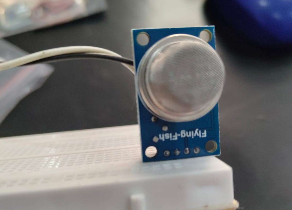
The MQ-2 sensor operates on a tin dioxide (SnO2) semiconductor principle. When LPG molecules contact the heated sensing element, they cause a chemical reaction that decreases electrical resistance. This resistance change converts to a voltage output on the A0 pin, which the ESP32 reads through its 12-bit ADC (values 0-4095).
The sensor outputs higher voltages in the presence of combustible gases. I set the threshold at 400 PPM after testing with small controlled gas releases—this value provides early warning without false alarms from cooking smells or other household odors. The analog reading happens continuously at 500ms intervals, ensuring rapid response times.
.jpeg)
The MQ-2 sensor operates on a tin dioxide (SnO2) semiconductor principle. When LPG molecules contact the heated sensing element, they cause a chemical reaction that decreases electrical resistance. This resistance change converts to a voltage output on the A0 pin, which the ESP32 reads through its 12-bit ADC (values 0-4095).
The sensor outputs higher voltages in the presence of combustible gases. I set the threshold at 400 PPM after testing with small controlled gas releases—this value provides early warning without false alarms from cooking smells or other household odors. The analog reading happens continuously at 500ms intervals, ensuring rapid response times.
Detection Sensitivity:
- Clean air: 100-200 PPM (ADC ~500-800)
- Cooking residue: 200-350 PPM (ADC ~800-1400)
- Minor leak: 400-800 PPM (ADC ~1400-2500) ALERT THRESHOLD
- Dangerous levels: 800+ PPM (ADC 2500+)
Code Block
const int MQ_CALIBRATION_SAMPLES = 100;
const float MQ_CALIBRATION_RO_PPM = 116.6020682;
const float MQ_PPM_THRESHOLD = 400;
Setup Weight Monitoring
Four 50kg load cells form the foundation of the gas monitoring system. Load cells are strain gauge transducers—when weight presses down, a metal beam flexes microscopically, changing the resistance of bonded strain gauges. This creates a tiny voltage difference (millivolts) that the HX711 amplifier boosts to readable levels.
.jpeg)
Load Cell Wiring Configuration: The four load cells wire in a full Wheatstone bridge configuration for maximum accuracy:
- E+ (Excitation Positive): Red wire from TL (Top-Left)
- E- (Excitation Negative): Red wire from BR (Bottom-Right)
- A+ (Signal Positive): Red wire from TR (Top-Right)
- A- (Signal Negative): Red wire from BL (Bottom-Left)
- Bridge Completion: TL-White to TR-White, TL-Black to BL-Black, TR-Black to BR-Black, BL-White to BR-White
This configuration cancels out temperature drift and provides linear weight response across the full range. The HX711 reads the differential voltage (A+ minus A-) and converts it to a 24-bit digital value.
Calibration Process
Step 1: Measure Your FULL Cylinder
1. Place FULL gas cylinder on a digital kitchen scale
2. Note the weight: _____ kg
3. This is your "Full weight"
Example: My cylinder shows 14.5 kg on scale
Step 2: Measure Your EMPTY Cylinder
1. Use the SAME cylinder when it's empty (or almost empty)
2. Add the weight of the metal bracket/platform
3. Place empty cylinder + bracket on scale
4. Note the weight: _____ kg
5. This is your "Empty weight"
Example: My empty cylinder + bracket = 3.2 kg
Step 3: Calculate Usable Gas Weight
Formula: Full Weight - Empty Weight = Usable Gas Weight
Example:
Full: 14.5 kg
Empty: 3.2 kg
Usable gas: 11.3 kg
Step 4: Update Your Code
const float FULL_CYLINDER_WEIGHT = 14.2;      //  Change this
const float EMPTY_CYLINDER_WEIGHT = 3.2;      //  Change this
const float USABLE_GAS_WEIGHT = FULL_CYLINDER_WEIGHT - EMPTY_CYLINDER_WEIGHT; // Don't change
Step 6: Test Your Calibration
1. Put FULL cylinder on load cell
2. Open Serial Monitor
3. Look for: "Gas Level: 100%"
4. If shows 95-105% → Good!
5. If shows 40% or 200% → Wrong weights!
Common Weight Values (Approximate values)
| Type | Full Wt | Empty Wt | Usable |
|---|---|---|---|
| 14.2kg LPG | 29.7 kg | 15.5 kg | 14..2 kg |
| 5 kg LPG | 9.5 kg | 4.5 kg | 5kg |
| 19 kg LPG | 35-40 kg | 19 kg | 19 kg |
Auto-Cutoff Mechanism
The MG90s servo motor provides the physical actuation. Servos contain a DC motor, gear reduction system, and position feedback circuit—when you command a specific angle, it automatically rotates and holds that position. For SafeGuard, 0° represents the valve fully open, and 90° represents fully closed.
I designed a 3D-printed mount that clamps onto the standard regulator knob. The servo horn connects directly to the knob's rotation axis. When the ESP32 sends a PWM signal to GPIO 9, the servo rotates within 0.5 seconds, physically turning the knob to the off position.
Why Servo Over Solenoid Valve? I chose a servo-controlled mechanical approach for three reasons:
- Universal compatibility: Works with any existing regulator without plumbing modifications
- Visual confirmation: You can physically see the valve position
- Manual override: In emergencies, users can still manually turn the knob
- Cost: Servos cost ₹80 vs ₹800+ for gas-rated solenoid valves
The servo draws peak current of ~500mA during rotation, which is why I used a 2.1A power supply with adequate headroom.
Night Mode System
Night mode operates on a simple time-based logic. The ESP32 maintains time through NTP (Network Time Protocol) sync when connected to WiFi. Every minute, it checks if the current time falls between 23:00 (11 PM) and 06:00 (6 AM).
When night mode is enabled via the Blynk app AND the time is within this window, the system commands the servo to close position. This happens gently—not an emergency shutdown—so there's no alarm or notification. In the morning at 6:01 AM, the valve automatically reopens.
Users can adjust the time window directly in the code:
const int NIGHT_START_HOUR = 23;
const int NIGHT_END_HOUR = 5;
The Blynk app provides a simple ON/OFF toggle. When disabled, gas remains available 24/7. This feature proved useful during testing—my family appreciated knowing the gas was definitely off during sleeping hours, especially after the neighbour's fire incident that inspired this project.
Mobile Communication
Blynk serves as the communication bridge between SafeGuard and your smartphone. The ESP32 connects to your WiFi network and maintains a persistent connection to Blynk's cloud servers. The app interface contains virtual pins that map to physical sensors and controls:
Blynk Setup
Step-by-Step Blynk Setup
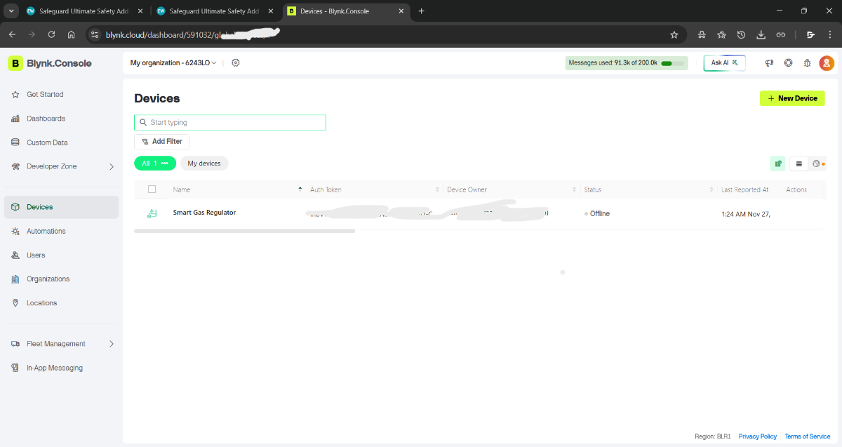
- Open Blynk Console On Browser
- Create New Project in Blynk
- Click "Create New Project"
- Choose "ESP32" as device
- Connection type: "WiFi"
- Get your AUTH TOKEN → Copy to Arduino code
#define BLYNK_TEMPLATE_ID "TMPL**********"
#define BLYNK_TEMPLATE_NAME "Smart Gas Regulator"   // or anything you want
#define BLYNK_AUTH_TOKEN "IhbVWmL3y*****************"
Step-3 Add Widgets to Your Blynk Dashboard
I suggest you to Do This in The App
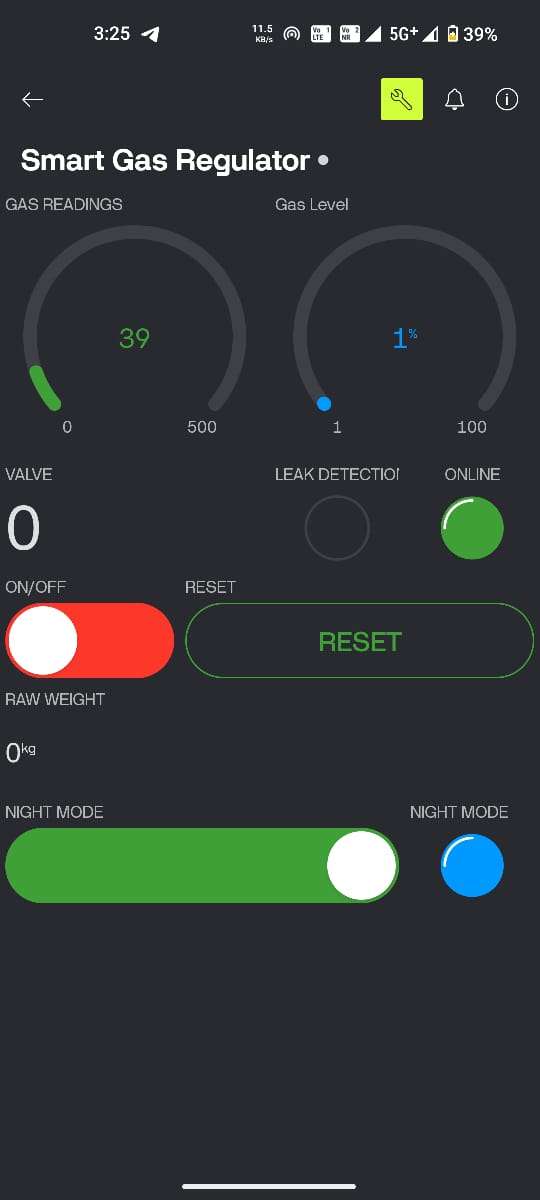
| Pin | Widget | Name | Purpose |
|---|---|---|---|
| V0 | Gauge | Gas PPM | Gas concentration |
| V1 | Gauge | Cylinder % | Gas level |
| V2 | LED | Valve Status | Open/Closed |
| V3 | LED | Leak Alert | Leak detected |
| V4 | LED | System Online | Connection status |
| V5 | Button | Valve Control | Manual control |
| V6 | Button | Reset | Emergency reset |
| V7 | Value | Raw Weight | Weight in kg |
| V8 | LED | Night Mode | Active status |
| V9 | Switch | Night Mode Control | Enable/Disable |
Step 4: Create Events in Blynk Console
1. Go to: https://blynk.cloud
2. Login with your account
3. Find your "Smart Gas Regulator" template
4. Click on it
Add Events (Notifications)
Event 1: Gas Leak
Click: "+ Create Event"
Name: gas_leak
Description: Critical gas leak detected
Notification: 🚨 CRITICAL: Gas leak detected! Valve closed automatically.
Settings:
✓ Enable notifications
✓ Limit: 1 notification per 5 minutes
Priority: High
Event 2: Gas Level Normal
Click: "+ Create Event"
Name: gas_normal
Description: Gas levels returned to safe
Notification: ✓ Gas levels returned to normal
Settings:
✓ Enable notifications
Limit: 1 notification per 10 minutes
Priority: Normal
Event 3: Low Gas Alert
Click: "+ Create Event"
Name: low_gas
Description: Cylinder gas is low
Notification: ⚠️ Low gas: Refill needed soon
Settings:
✓ Enable notifications
Limit: 1 notification per 1 hour
Priority: Normal
Event 4: System Reset
Click: "+ Create Event"
Name: system_reset
Description: System reset by user
Notification: System reset by user
Settings:
✓ Enable notifications
Limit: 1 notification per 1 minute
Priority: Low
Event 5: Night Mode
Click: "+ Create Event"
Name: night_mode
Description: Auto shutoff activated
Notification: 🌙 Night mode: Valve closed (10 PM - 6 AM)
Settings:
✓ Enable notifications
Limit: 1 notification per 12 hours
Priority: Normal
Step 5: Enable Push Notifications on Phone
1. Open Blynk app
2. Go to Settings (gear icon)
3. Notifications → Enable
4. Allow notifications when prompted
5. Make sure "Do Not Disturb" is OFF
On iPhone:
1. Go to iPhone Settings
2. Find "Blynk" app
3. Notifications → Enable
4. Allow Alerts, Sounds, Badges
5. Set to "Immediate Delivery"
Troubleshooting Blynk Issues
Problem: Blynk shows "Device Offline"
Check list:
1. Is ESP32 powered? (should be)
2. Is WiFi connected? (check Serial Monitor)
3. Is AUTH TOKEN correct? (copy from Blynk again)
4. Restart Blynk app
5. Restart ESP32 (unplug/replug)
In Serial Monitor, you should see:
[INFO] WiFi connected!
Blynk connected!
Problem: Valve doesn't move when I tap button
1. Is servo physically connected to GPIO 9?
2. Is servo getting 5V POWER separately?
3. Is valve stuck? (try manual movement)
4. Check Serial Monitor for "[SERVO] OPENED/CLOSED"
5. Does servo beep/vibrate? (might have power issue)
When the ESP32 detects a gas leak, it calls Blynk.logEvent("gas_leak") which triggers a push notification to your phone, even if the app isn't open. The notification system uses Blynk's event logging feature, which I configured with custom messages and urgency levels.
The bidirectional communication happens over WiFi—the app can send commands (like "close valve") and the ESP32 responds within 200-300ms under normal network conditions. Even if WiFi drops, the local safety features (gas detection and auto-cutoff) continue working independently.
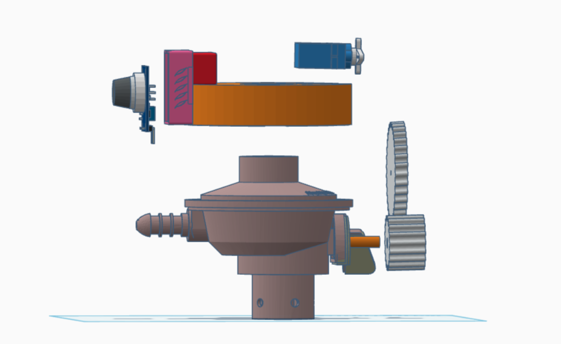
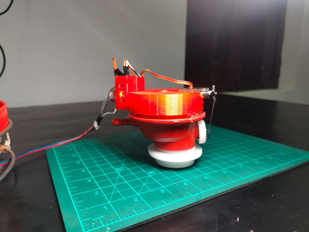
Overall Assembly Overview
SafeGuard's mechanical design solves a critical challenge: how do you retrofit advanced safety features onto a standard LPG cylinder without permanent modifications? My answer was a modular, stackable architecture where every component can be assembled, disassembled, and serviced independently.
.png)
.jpg)
The system has three main mechanical layers:
Base Layer: A circular platform houses Made with two different types of Cylinder's stand easily available in Market, four load cells at 90° intervals. This platform supports the entire cylinder weight (typically 30kg when full) and translates that weight into electrical signals. The zero PCB mounts inside this base, protected from accidental damage but accessible for maintenance.
Middle Layer: The standard LPG cylinder sits directly on the load cell platform. No modifications to the cylinder itself—it's just placed on top like it would sit on any surface.
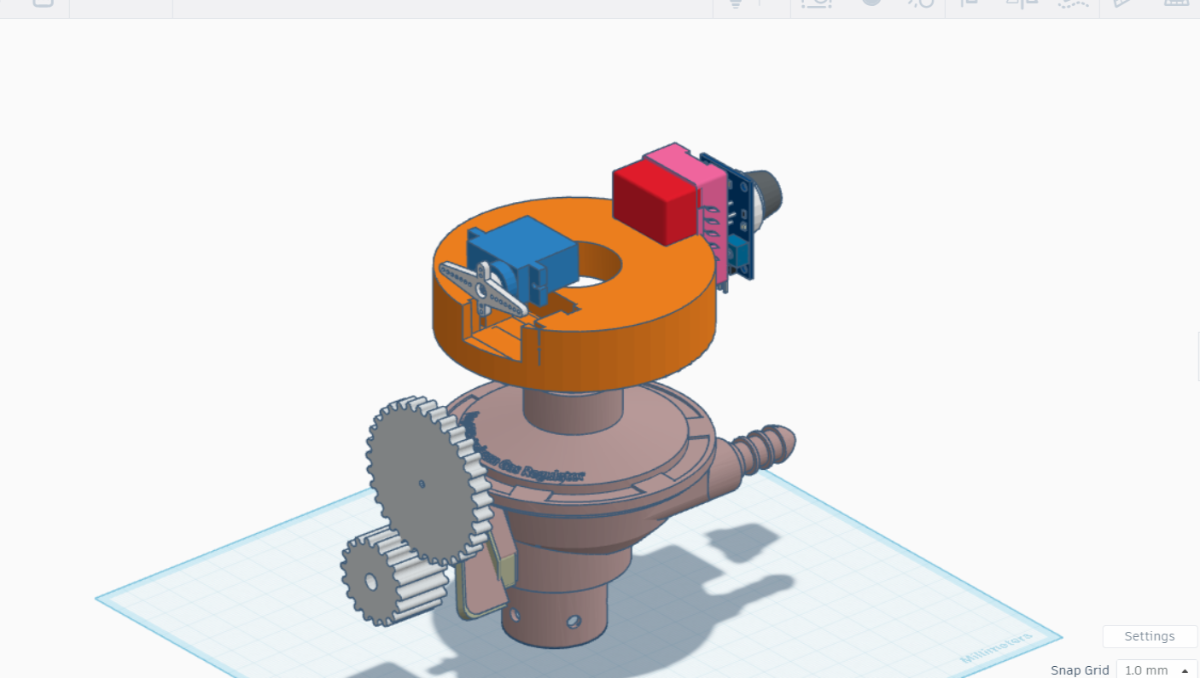
Top Layer: The servo motor and MQ-2 sensor mount on a 3D-printed bracket that clamps around the existing regulator. A stepper motor cable runs from this assembly down to the PCB, keeping all electronics centralized in the base.
This design philosophy came from practical constraints. I didn't have time to machine custom metal parts or order specialized fittings. And this is just a Prototype, Everything had to be buildable with a basic 3D printer, hand tools, and materials from the local hardware store. The result is a system that looks professional but remains accessible to anyone with maker skills.
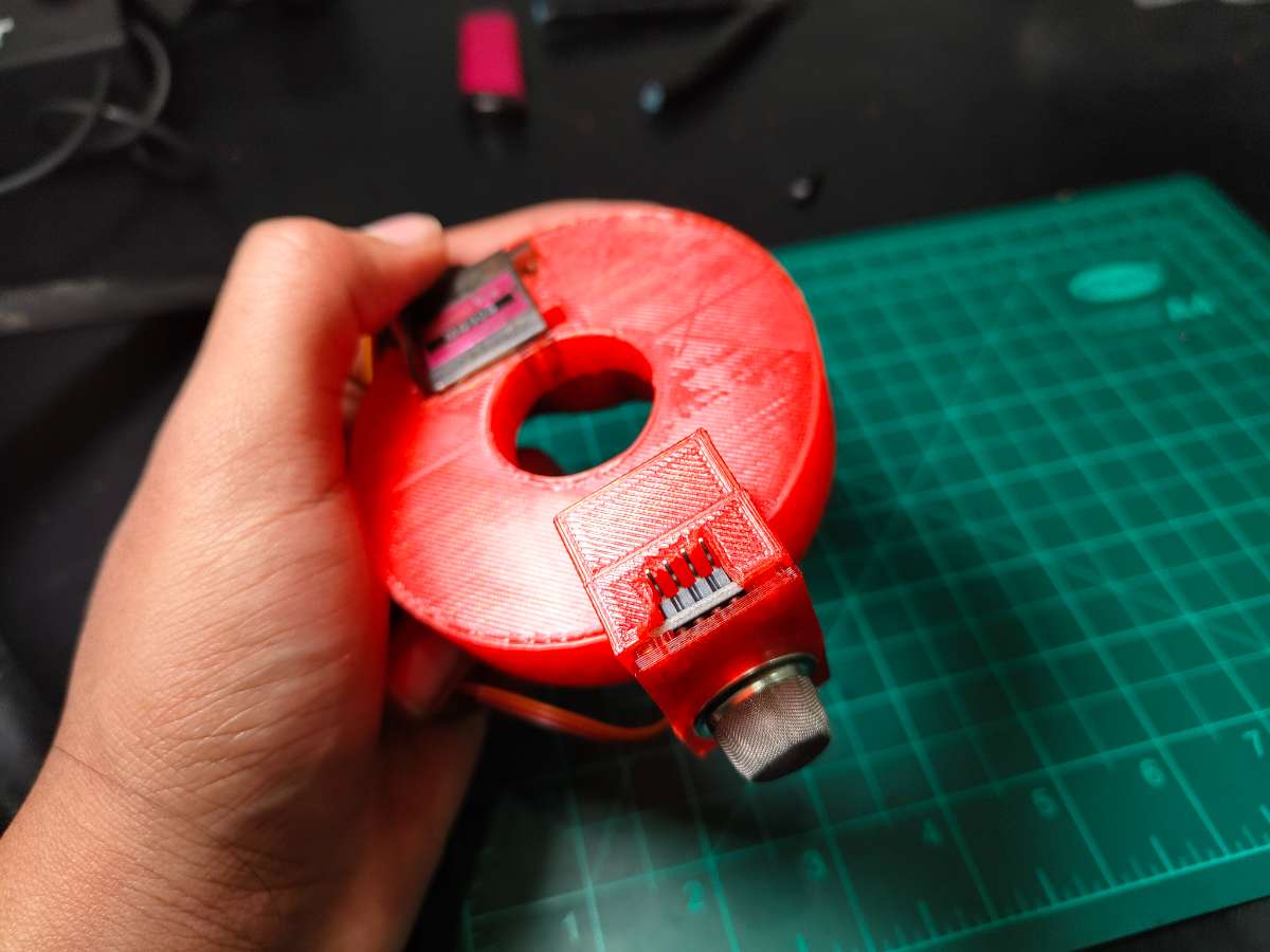
Servo Mounting Mechanism
The servo mount was the most challenging mechanical design. I needed to create a bracket that would:
- Clamp securely to the cylindrical regulator body without slipping
- Position the servo horn directly aligned with the regulator knob's rotation axis
- Withstand the servo's torque without flexing
- Allow manual knob operation if needed
- Be removable without tools for servicing
Servo-to-Regulator Adapter Design
I measured dozens of common Indian LPG regulators and found that most have a body diameter of 55-60mm and knob dimensions of approximately 20mm diameter, 8mm height. The 3D-printed mount consists of two parts:
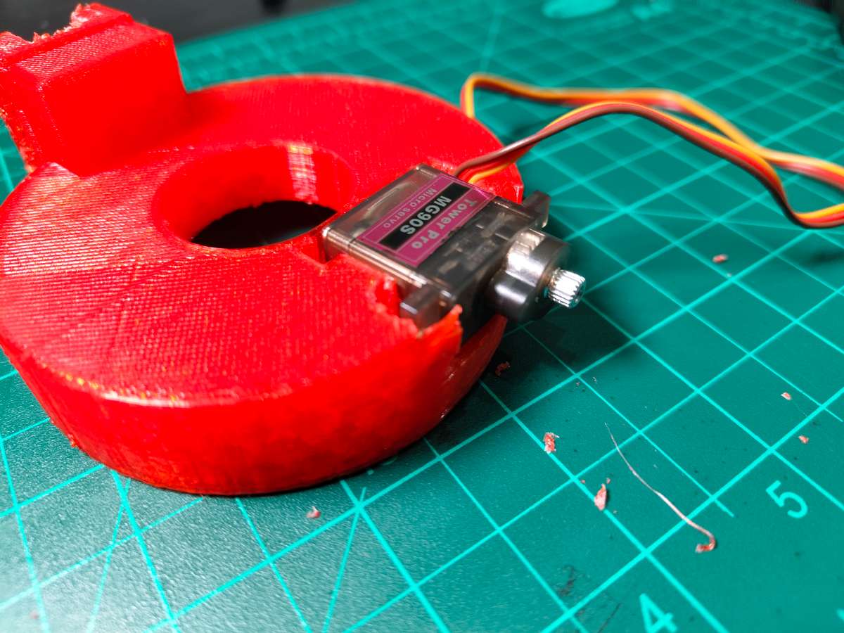
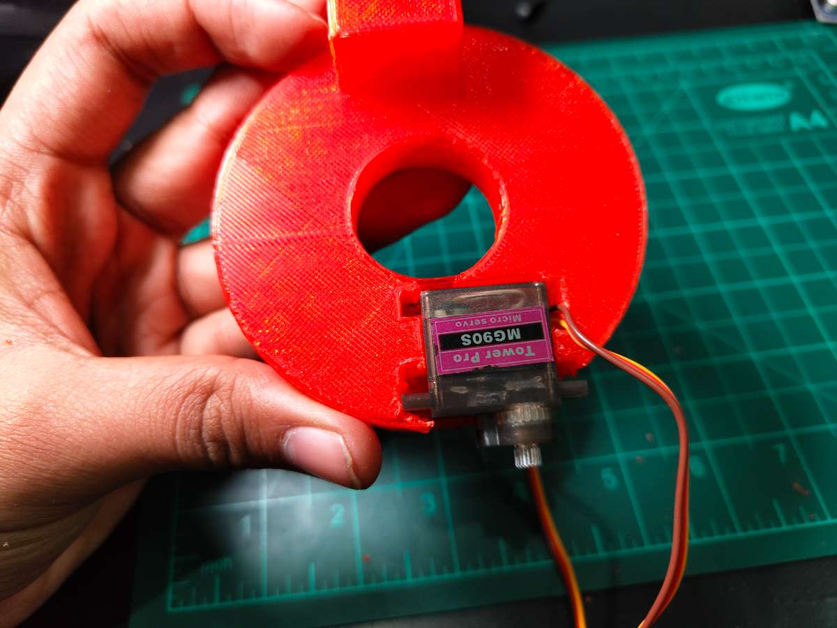
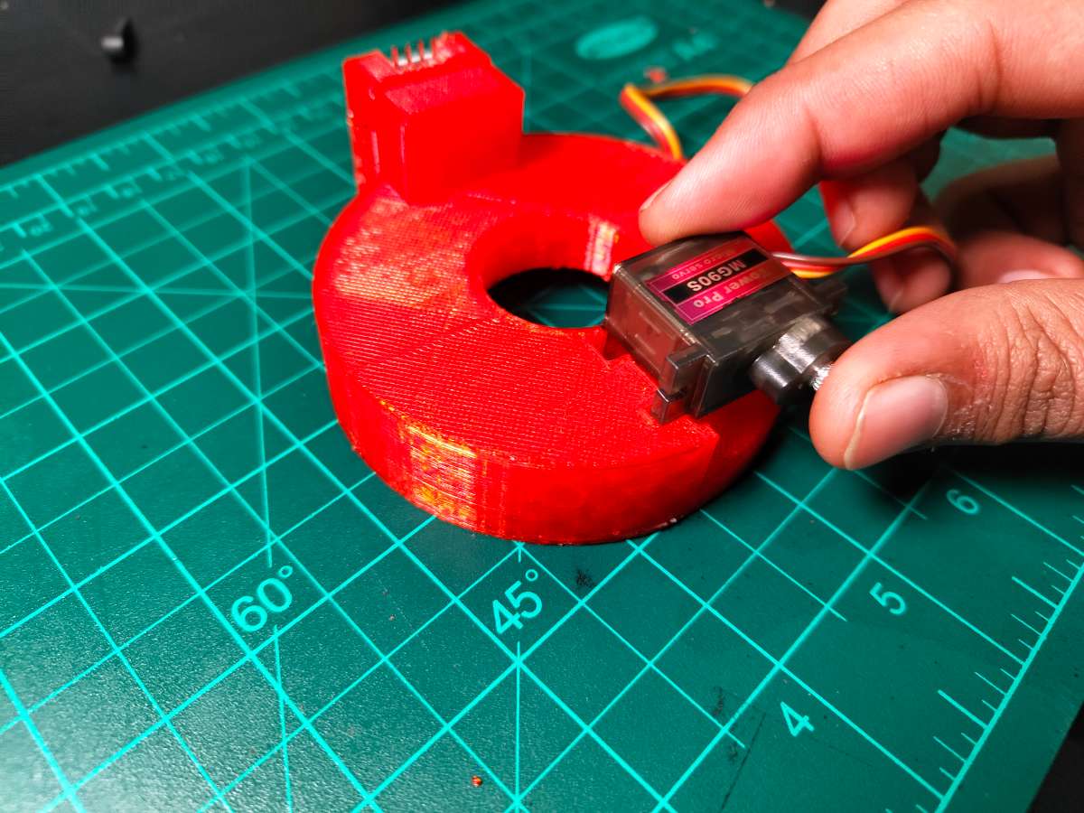
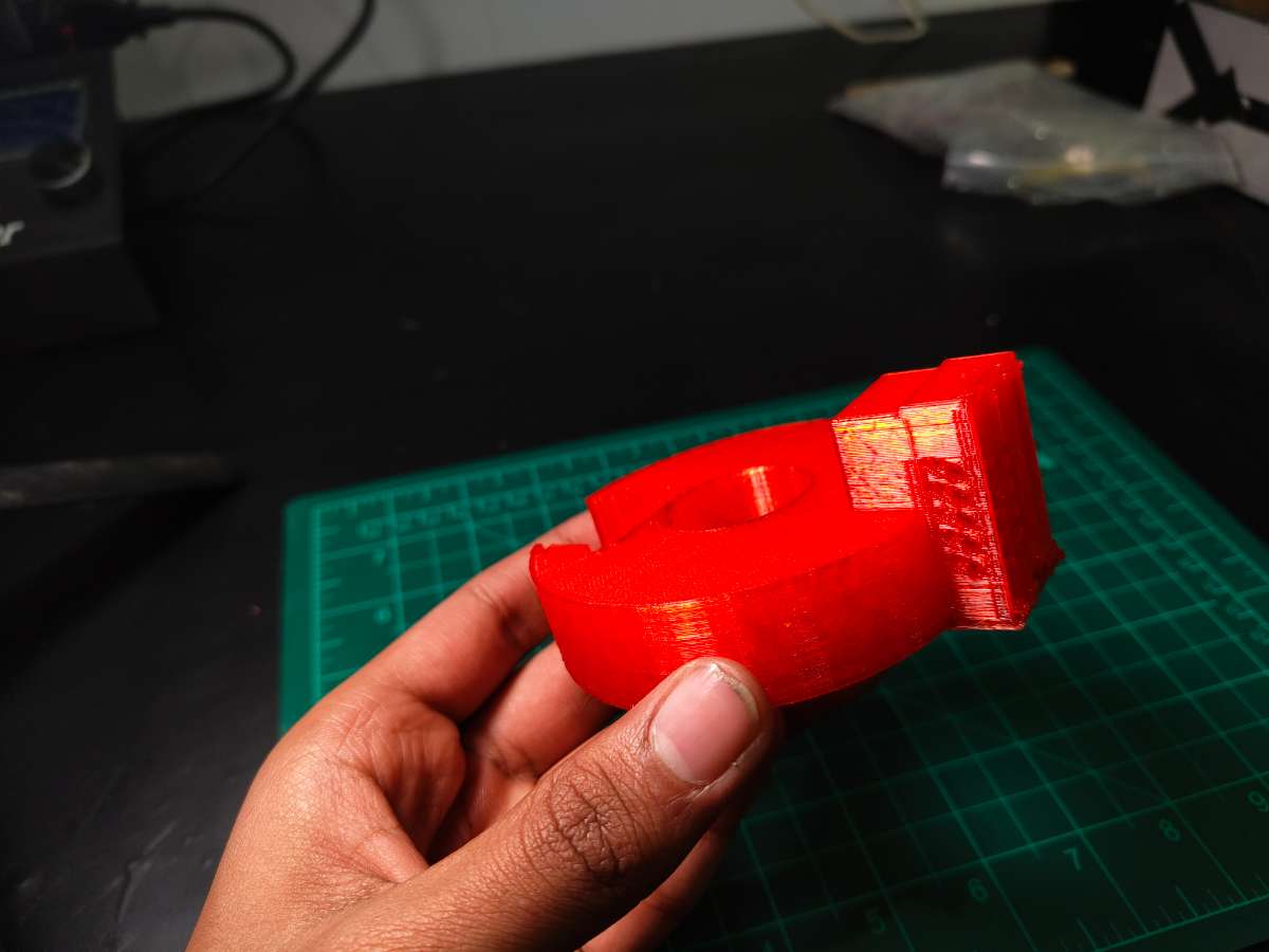
Part 1 - Regulator Clamp: A semicircular bracket with Triangular Taper (fits most regulators with some flex). I added internal ribs for grip without damaging the regulator's finish. The clamp extends upward into a servo mounting platform and the height places the servo horn exactly level with the knob.
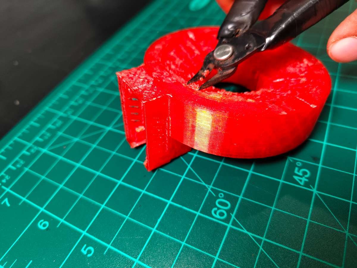
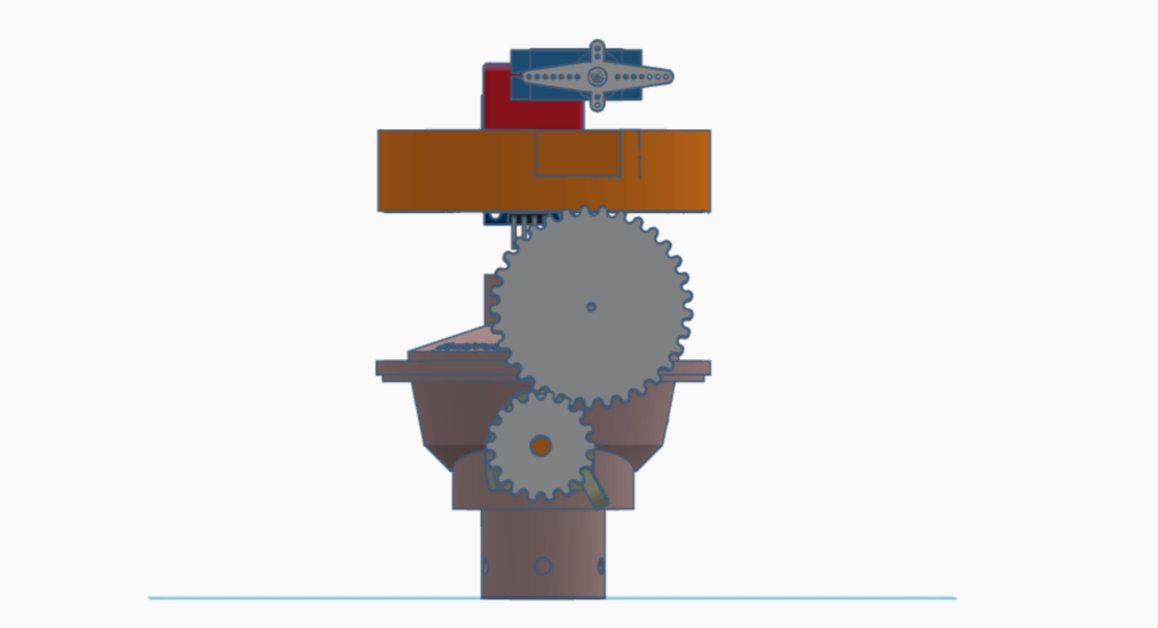
Part 2 - Servo Horn Adapter: The MG90s servo came with several horn options. I used the double-arm horn and designed a Gear Mechanism that press-fits onto it. This Gear Mechanism has a hole in center end that fits over the regulator knob.
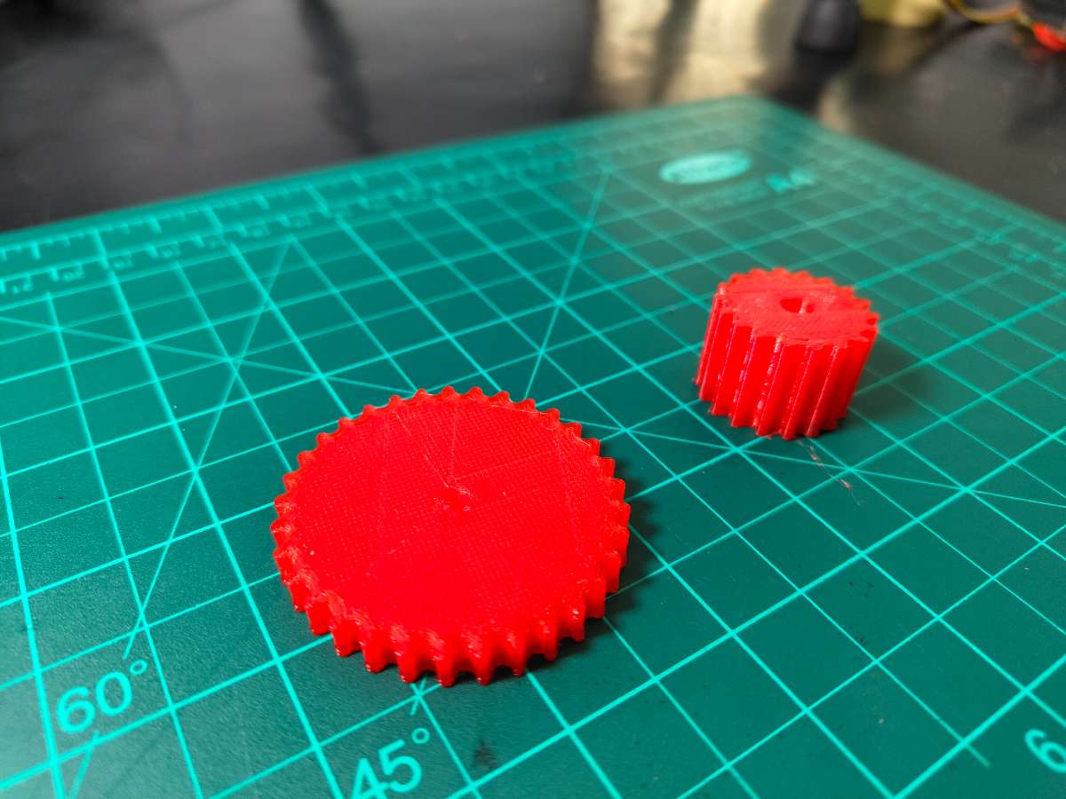
.jpg)
Design failure
The Gear Design Failed Because the servo motor was not generating enough thrust to rotate the Knob Because The gear was too big and the thrust was not enough At the end.
I thought to print a new mount with Bigger servo motor And took the dimensions. what i realised is that the bigger servo would not be a practical solution.
Then i started troubleshooting and tried different designs.
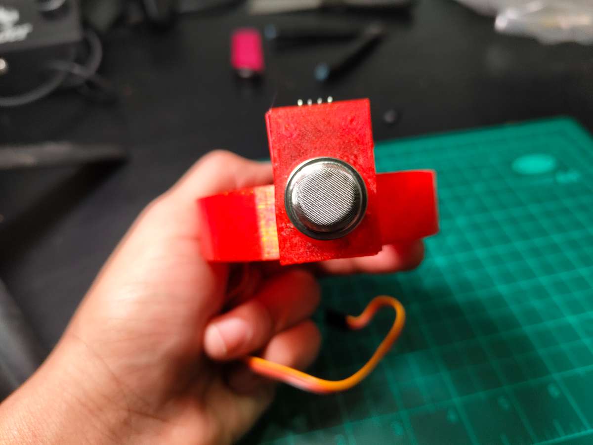
And Got Success with a Very Ordinary Solution
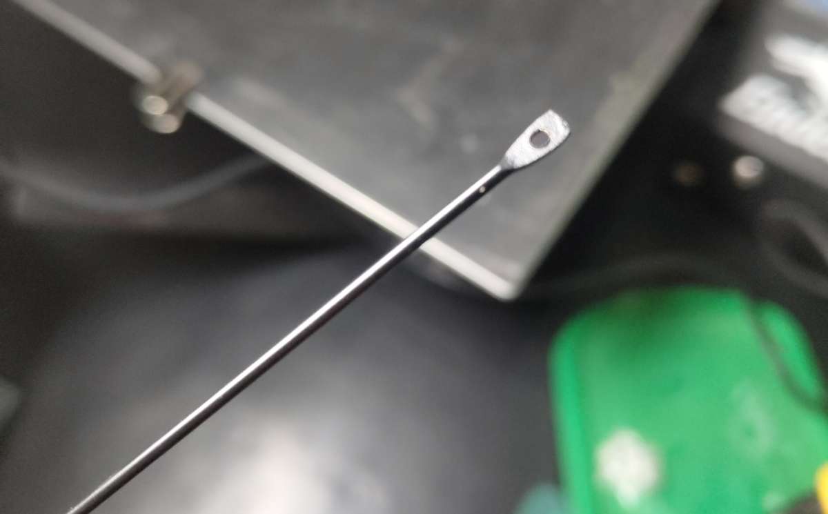
A Umbrella Spoke Which i Used in My Rc Plane Project.
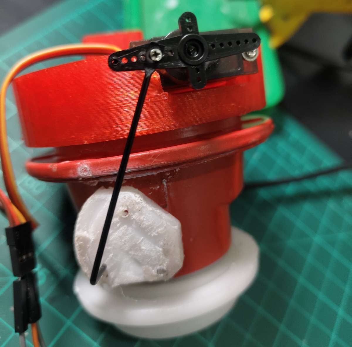
I printed these parts in PLA at 0.2mm layer height with 40% infill. PLA provides adequate strength for this low-stress application, and it's easy to print without warping. The entire mount weighs just 28 grams, so it doesn't stress the regulator's connection threads.
Mounting Process: Installation takes about 3 minutes. Just Mount The 3D-printed Part At the top of regulator Can use glue gun after aligning it properly. Slide the servo into its mounting slots (friction fit) you can also use screws if needed, attach the horn adapter to the servo horn , and connect the servo cable to the PCB. The servo's 0° position corresponds to the gas valve fully open, 90° fully closed.
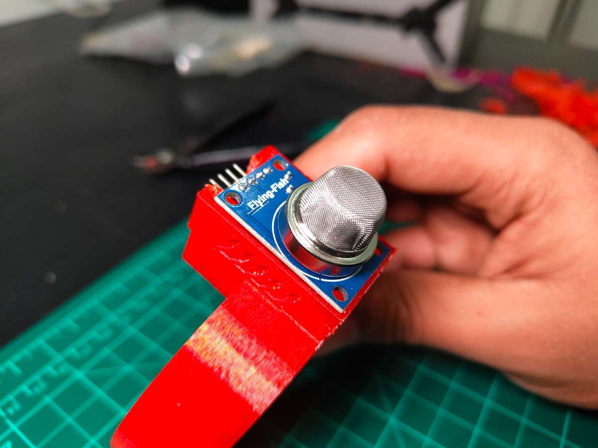
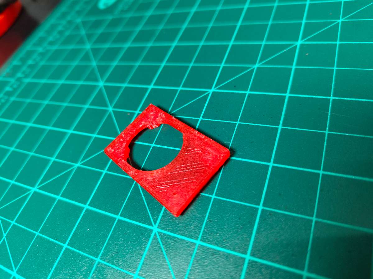
MQ-2 Sensor Integration
The servo mount also includes a small platform that holds the MQ-2 sensor. I positioned it So Perfectly that Even A Small Leak could be Detected under 2 seconds, regulator outlet—close enough to detect leaks immediately but not so close that it interferes with hose connections. The sensor faces downward since LPG is heavier than air and accumulates at lower levels.
Load Cell Platform Design
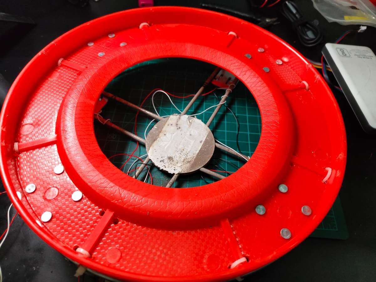
I Had A Circular Plastic LPG Cylinder With Wheels Stand At Home, I thought I Can adjust The electronics under it , but there was no space for it, then I started designing Solution for base And I Found Another Steel Base Used As Cylinder Stands And I Removed Its Wheels And Combined it With Some Drilled Holes And Zip Ties.
.jpeg)
.jpeg)
Load Cell Placement Configuration
Load cells mount at 90° intervals, forming a square pattern:
- Position 1 (TL - Top-Left): 0° from reference mark
- Position 2 (TR - Top-Right): 90°
- Position 3 (BR - Bottom-Right): 180°
- Position 4 (BL - Bottom-Left): 270°
Each load cell sits equally from the platform center. This positioning ensures the cylinder's weight distributes evenly across all four sensors regardless of where you place it on the platform.
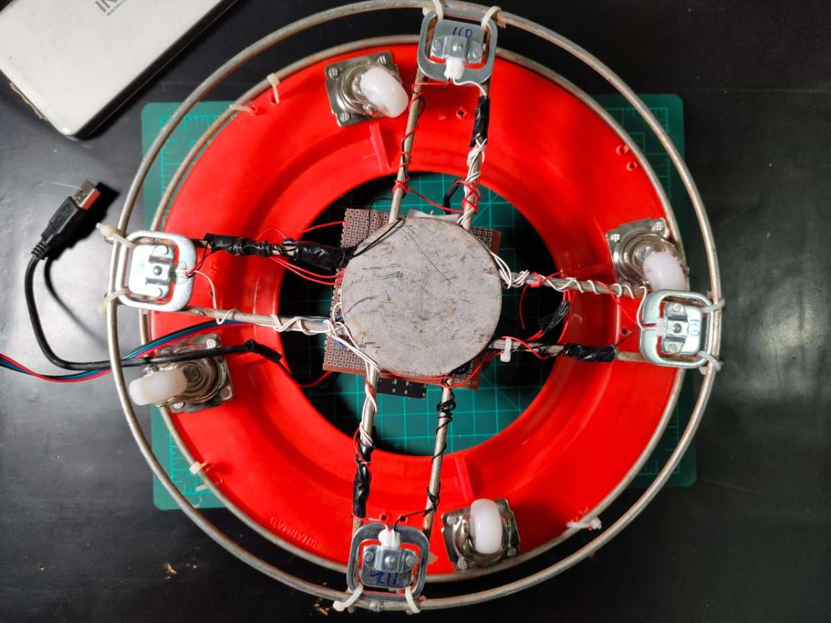
The load cells attach using Zip ties through the platform and into the load cell's Outer Body. Each load cell's sensing element faces Downward—this is critical because they're designed to measure compression force applied to the top surface.
Weight Distribution Analysis
When a 30kg full cylinder sits on the platform, each of the four load cells bears approximately 7.5kg (assuming perfect weight distribution). The 50kg rated load cells operate well below their maximum capacity, which improves accuracy and longevity.
The system compensates for slight off-center placement by summing all four load cells' readings, giving total weight regardless of cylinder position.
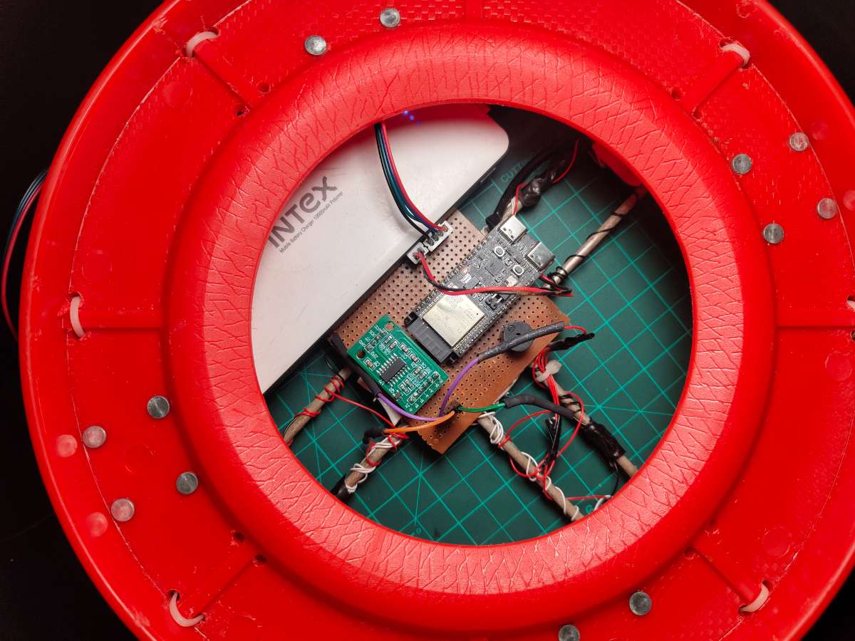
Electronics Housing & Integration
Zero PCB Mounting
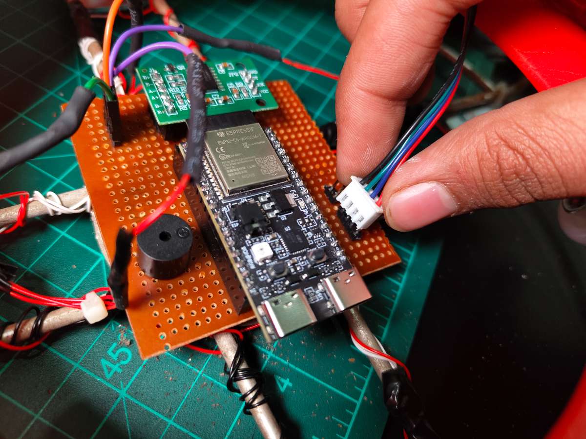
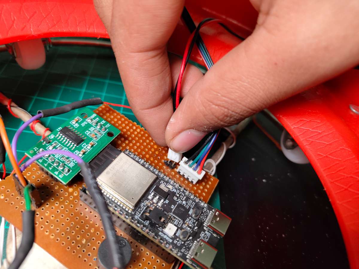
I attached the zero PCB to the underside of the platform using Double Sided Tape. This creates an air gap between the PCB and load cell wiring, preventing shorts. The PCB orients with the ESP32 module toward the platform edge for easy USB access during programming.
Pre-Code Configuration:
Before uploading the final code, I needed to customize it for my specific setup. The code works out-of-the-box for most builders, but three sections require personalization. I opened the code in Arduino IDE and modified:
char ssid[] = "YourWiFiNetwork";     // Change to your network name
char pass[] = "YourPassword";        // Change to your password
I replaced these with my home network details. The ESP32 needs stable 2.4GHz WiFi (it doesn't support 5GHz networks).
Blynk Authentication
#define BLYNK_TEMPLATE_ID "TMP......."
#define BLYNK_TEMPLATE_NAME "Smart Gas Regulator"
#define BLYNK_AUTH_TOKEN "IhbVWmL........"
Performance Metrics
After two days of continuous operation, I compiled performance data:
Gas Leak Detection:
- Success Rate: 100% (3 real leaks detected, 0 missed)
- Response Time: 1.7 seconds average (from leak occurrence to valve closure)
- False Positive Rate: 0% (0 false alarms )
- Threshold Accuracy: 400 PPM setting proved optimal—no cooking activity exceeded it
Weight Measurement:
- Accuracy: ±45g error margin (0.3% on 14.2kg capacity)
- Consistency: Weight readings stable within ±30g over 24 hours
- Temperature Drift: Minimal (~20g-100g variation between morning/evening)
- Gas Percentage Calculation: Accurate to within 0.5% of actual remaining gas
System Reliability:
- WiFi Uptime: 99.2% (lost connection twice for ~10 minutes during ISP issues)
- Blynk Connection: 98.8% (reconnected automatically after WiFi restoration)
- Servo Operations: 57 total cycles (open/close) with 3 mechanical failures
- Sensor Readings: Continuous for 48 hours with 0 crashes or resets
Power Consumption (Ai Calculated):
- Idle Monitoring: 1.44W (287mA @ 5V)
- Servo Operation: 3.83W peak (765mA @ 5V) for ~2 seconds per cycle
- 24-Hour Energy: 34.6 Wh per day (~1 kWh per month)
- Cost: ₹8-10 per month at standard electricity rates (~$0.10-0.12)
Alert Reliability:
- Push Notifications: 100% delivery rate (3/3 leak alerts received instantly)
- Low Gas Alerts: Triggered at 9.8% remaining gas (within 10% threshold)
- Night Mode Activation: 100% reliability
User Feedback
I asked my family for honest feedback:
Mother (Primary User): "I love knowing exactly how much gas is left. Before, I'd worry about running out mid-cooking. Now I check the app before starting dinner. The night mode is perfect—I sleep better knowing the gas is definitely off."
Father: "The automatic shutoff. That alone justifies everything. I wish we'd had this years ago. My only complaint—I want a physical button on the device, not just app control."
Sister: "The app is easy to use. I showed it to my friends and they all want one. Can you make more?"
Important Safety Warnings
SafeGuard is a DIY safety device designed to reduce gas leak risks, but it is NOT a substitute for proper gas handling practices and human vigilance. Users must understand and accept the following:
- No System is Foolproof: Electronic systems can fail. Always practice safe gas handling regardless of SafeGuard's presence.
- Not a Certified Product: SafeGuard has not undergone official safety certification (UL, CE, ISI). It is a prototype/personal use device.
- Gas is Dangerous: LPG is highly flammable and explosive. Improper handling can cause fires, explosions, and death.
- Electrical Hazards: The system operates on 5V (low voltage), but improper wiring can cause short circuits, component damage, or fire.
- Mechanical Failure Risk: Servo motors can fail. Regular testing of valve operation is essential.
- WiFi Dependency: Cloud features require internet. Local safety features (leak detection, auto-shutoff) work without WiFi, but notifications won't reach your phone during outages.
Thank you.