


Introduction: The Challenge of Precision
Many drones rely entirely on GPS to know their location. But what happens when you fly indoors or under a dense canopy? The drone drifts. Our goal was to build a UAV that acts intelligently in these environments. We achieved this by using edge computing and ground-tracking sensors to create a vehicle that "sees" the floor and holds its position autonomously.
Step-by-Step Build Process
1. The Flight Controller and Power Core
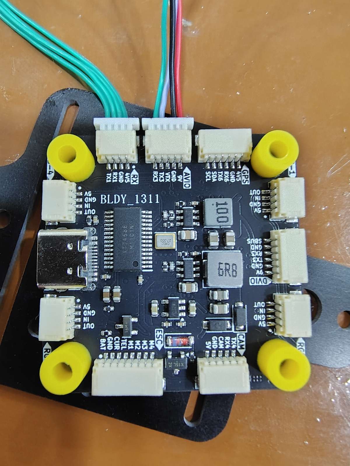
We started with the Botwing F405 flight controller as our main brain. Since we use a 3S 5200 mah battery for extended flight times, we carefully calibrated the analog voltage sensors and failsafe limits directly in the firmware to ensure safe operations. The motors and XT60 connectors for Lipo battery with capacitor are soldered onto a Botdrive 32 bit 4 in 1 ESC which is connected to the FC through JST connectors provided in the box.
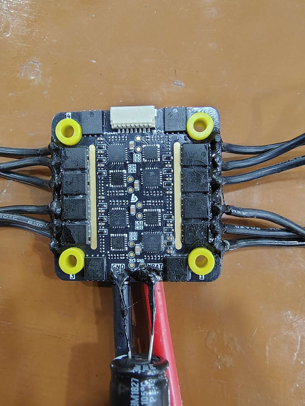
Important Note: Make sure to double check you ESC soldering with continuity tester with a multimeter making sure there are no bridges as they may result in burning out the ESC. And never forget to solder a good quality Capacitor with correct polarity on to the power supply pads. You can refer this video for in detail ESC Soldering Tips.
We need to flash the latest and stabke version of Ardupilot firmware onto the FC before and setup is done. Arducopter Firmware
2. Establishing the Telemetry Bridge
Standard radio telemetry can be incredibly slow for downloading complex parameters. We integrated a Raspberry Pi 4 as a companion computer. We connected it directly to the flight controller via USB to handle heavy data processing.
Note: The Rpi4 used here is running on Ubuntu 22.04 for running ROS2 humble and Open CV. I haven't shown the Rpi setup here as it can be very easily found on Youtube and ROS documantation.
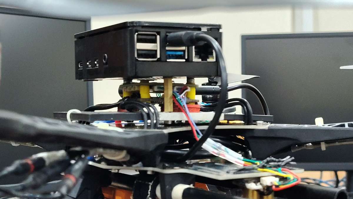
Important Note: A Raspberry Pi 4 draws up to 3 Amps. It must be powered by a dedicated 5V BEC(LM2596 DC-DC Step Down Buck Converter is used here), not directly from the flight controller, to prevent mid-air brownouts.
We bypassed traditional Windows networking bottlenecks by setting up a TCP server on the Pi. Here is the exact command we run on the Pi to broadcast high-speed MAVLink data to our ground station:
Bash
sudo mavproxy.py --master=/dev/ttyACM1 --baudrate 115200 --out=tcpin:0.0.0.0:5760
3. Integrating Optical Flow for GPS-Denied Flight
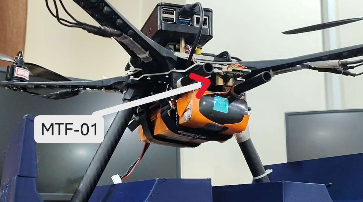
To stop the drone from drifting, we mounted an MTF-01 optical flow and LiDAR sensor facing the ground.
We calibrated the gyro scaling so the camera perfectly subtracts the drone's pitch and roll from the ground movement. This allows the flight controller to lock onto the texture of the ground, resulting in a rock-solid hover without any GPS satellites.
You need to setup the MTF-01 sensor Parameters in Mission Planner before it can be used.
Here is the exact parameter checklist you need to punch into the Full Parameter Tree in Mission Planner.
3.1. The Hardware Serial Port
Assuming you wired the MTF-01 to SERIAL2 (UART2) on the flight controller, configure the port to read incoming MAVLink packets:
SERIAL2_PROTOCOL=1(MAVLink 1)SERIAL2_BAUD=115(Sets the baud rate to 115200)SERIAL2_OPTIONS=0(Note: If you are running an older ArduPilot version like 4.5.x, you may need to set this to1024to prevent it from forwarding MAVLink data incorrectly).
3.2. Activate the Sensors
You must turn on both the Optical Flow camera and the LiDAR rangefinder separately so Mission Planner knows they exist.
Optical Flow Configuration:
FLOW_TYPE=5(Expect MAVLink optical flow data)
Rangefinder (LiDAR) Configuration:
RNGFND1_TYPE=10(Expect MAVLink distance data)RNGFND1_MIN_CM=5(Minimum reliable reading is 5cm)RNGFND1_MAX_CM=800(Maximum reliable reading is 8 meters)RNGFND1_ORIENT=25(Tells the drone the LiDAR is pointing straight down to the floor)
CRITICAL STEP: Once you input these, click Write Params and physically unplug the drone's battery to reboot it. The next set of parameters will not appear until ArduPilot restarts and detects the active sensors.
3.3. The EKF3 Fusion (The "Brain" Math)
Just because the sensors are on doesn't mean the drone is using them to fly. We are going to set up "Source 2" in the Extended Kalman Filter as your dedicated GPS-denied navigation profile.
Search for the EK3_SRC2_ parameters and set them exactly like this:
EK3_SRC2_POSXY=0(None - we aren't getting absolute GPS coordinates)EK3_SRC2_POSZ=2(RangeFinder - use the LiDAR for altitude hold)EK3_SRC2_VELXY=5(OpticalFlow - use the camera for horizontal speed tracking)EK3_SRC2_VELZ=0(None)EK3_SRC2_YAW=1(Compass - rely on your onboard magnetometer for heading)
3.4. Switch Setup (RadioMaster Pocket)
To actually use this, you need a way to tell the drone to stop looking for GPS satellites and start looking at the floor. Assign a switch on your RadioMaster Pocket to toggle the EKF source.
RC6_OPTION=90(Assuming you use Channel 6. This maps the switch to "EKF Pos Source". Low is GPS, Middle is Optical Flow).
⚠️ The MicoAssistant Firmware Trap
If you finish all of this, look at your Mission Planner HUD, and the
sonarrangeandopt_m_xvalues are completely dead/frozen at zero, you have fallen into the System ID trap.
If you are running ArduPilot 4.5 or newer, it will actively ignore the MTF-01 if it shares the default System ID of 1.
- Connect the MTF-01 directly to your PC using a USB-to-TTL adapter.
- Open the official MicoAssistant software.
- Ensure the protocol is set to
Mav_APM. - Change the
Sys idfrom1to200. Hit write. The sensor will instantly come alive in Mission Planner!
Project Outcome & Demonstration
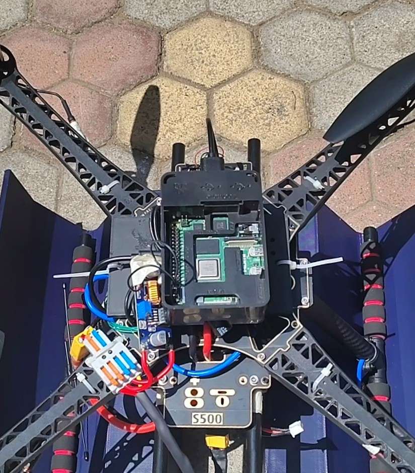
The final result is a drone that can be commanded via a high-speed telemetry link and hold its position flawlessly in complex environments.
Computer Vision & ROS Implementation
4. Simulating Autonomous Behavior in Gazebo
Before testing on the actual quadcopter, we built a digital twin of our UAV inside the Gazebo simulation environment. This allowed us to safely test our autonomous control loops, node communications, and sensor failure scripts without risking hardware damage. I also tested for swarm integration in the Gazebo Physics simulator.
Our ROS architecture uses a dedicated node to subscribe to sensor data from the flight controller, compute navigation vectors, and send overriding waypoint commands back over the MAVLink bridge in real time.
5. Real-Time Feature Mapping Pipeline
For physical deployment, the companion computer processes live visual data using OpenCV. Because the drone operates in environments without GPS, the software detects high-contrast geometric points on the ground to track position changes as well as feature mapping for different ground surface and texture.