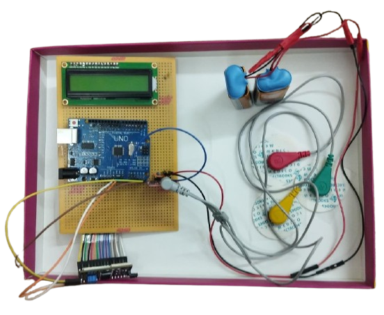
The above is the Final Working Output Video of Virtual Reflex Machine
Workflow:
- Electrode Placement
Surface EMG electrodes are placed on the forearm muscles to detect electrical signals produced during muscle contraction. Two electrodes act as active sensors, while one reference electrode is placed on the wrist to reduce noise. - EMG Signal Acquisition
The EMG sensor module amplifies and filters the weak muscle signals received from the electrodes, producing a clean analog output suitable for processing. - Arduino Interface
The amplified EMG output is connected to the Arduino Uno through analog pin A0. The Arduino continuously monitors the signal and detects muscle activation when the value crosses a predefined threshold. - LCD Display Connection
A 16×2 LCD with an I2C module is connected to the Arduino to display system messages and the measured reaction time in milliseconds. - Programming the System
Arduino code is uploaded to:- Generate a random delay before stimulus presentation
- Start the timer when the cue appears
- Monitor EMG signals continuously
- Stop the timer upon muscle activation
- Display the reaction time on the LCD
- VR Stimulus Integration
A VR headset provides visual or auditory cues such as race-start signals or flashing indicators, creating an immersive sports-training environment. - Reaction Time Measurement
When the participant responds by flexing the forearm muscle, the EMG sensor detects the contraction and the Arduino calculates the delay between stimulus and response using themillis()function. - Result Display and Analysis
The measured reaction time is displayed instantly on the LCD and can be recorded for analyzing reflex speed, fatigue, and hand dominance.
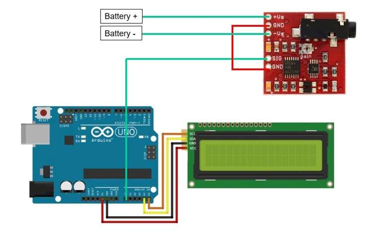
The following is the circuit connection (schematic diagram):
- Battery + --> +Vs (EMG sensor)
- Battery - --> -Vs (EMG Sensor)
- GND (EMG Sensor) --> GND (EMG Sensor)
- SIG (EMG Sensor) --> A0 (Arduino UNO)
- SCL (LCD) --> A5 (Arduino UNO)
- SDA (LCD) --> A4 (Arduino UNO)
- GND (LCD) --> GND (Arduino UNO)
- Vcc (LCD) --> 5V (Arduino UNO)
Final Output: