
video
Connect the circuit as per pins from Microcontroller port number to 7 Segment display as described below
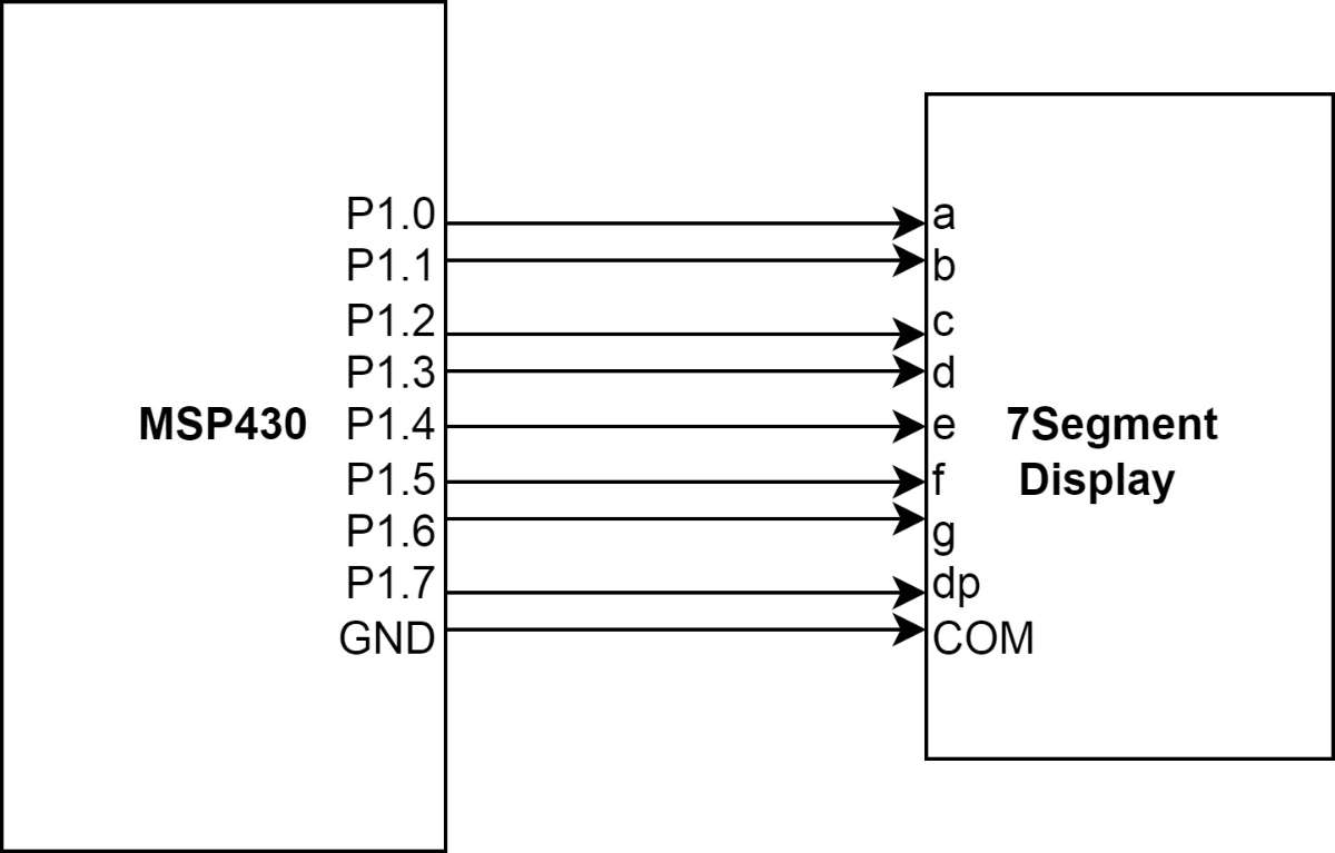
MSP430 -> 7 Segment Display Connection
P1.0 -> a Segment
P1.1 -> b Segment
P1.2 -> c Segment
P1.3 -> d Segment
P1.4 -> e Segment
P1.5 -> f Segment
P1.6 -> g Segment
P1.7 -> DP Segment
2 COM pins of 7 Segment shorted and connected to Ground of MSP430 if it is Common Anode 7 segment display
code
#include <msp430.h>

int main(void) {
    WDTCTL = WDTPW | WDTHOLD;   // Stop watchdog timer
   P1DIR|=0XFF;
    while(1)
    {
        volatile unsigned long i;
        P1OUT &=0x00;
        P1OUT =0x6F & 0XFF;
               i = 50000; // SW Delay
                                do i--;
                                while(i != 0);
        P1OUT =0x7F & 0XFF;
               i = 50000; // SW Delay
                                do i--;
                                while(i != 0);
        P1OUT =0x07 & 0XFF;
               i = 50000; // SW Delay
                                do i--;
                                while(i != 0);
        P1OUT =0x7D & 0XFF;
               i = 50000; // SW Delay
                                do i--;
                                while(i != 0);
        P1OUT =0x6D & 0XFF;
               i = 50000; // SW Delay
                                do i--;
                                while(i != 0);
        P1OUT =0x66 & 0XFF;
               i = 50000; // SW Delay
                                do i--;
                                while(i != 0);
        P1OUT =0x4F & 0XFF;
               i = 50000; // SW Delay
                                do i--;
                                while(i != 0);
        P1OUT =0x5B & 0XFF;
        i = 50000; // SW Delay
                        do i--;
                        while(i != 0);
        //P1OUT &=0X00;
        P1OUT =0x06 & 0xFF ;
        i = 50000; // SW Delay
                        do i--;
                        while(i != 0);
        P1OUT =0x3F & 0XFF;
        i = 50000; // SW Delay
                        do i--;
                        while(i != 0);
    }
    return 0;
}