
Description
Overview
A smart self-watering planter featuring a 3D-printed pot, integrated bottom water reservoir, and an ESP32-based control system. A capacitive soil moisture sensor continuously monitors soil conditions and automatically activates a mini water pump when the soil becomes dry keeping your plant hydrated with minimal manual effort.
Project Concept
This project builds a compact indoor planter that can water itself automatically. The planter body, reservoir, electronics enclosure, and sensor holders are manufactured using a Bambu Lab 3D printer, while the control logic is handled by an ESP32 that reads soil moisture and switches a pump on only when needed.
The main goal is to reduce manual watering and make the planter neat, compact, and reusable. Since the water tank is integrated into the printed structure, the final build looks much cleaner than using a separate bottle, tray, or external container.
See also: ESP32 IoT Projects on ElectronicWings
Working Principle
A capacitive soil moisture sensor is inserted into the soil to measure how dry or wet the soil is. The ESP32 continuously reads this analog value and compares it against a pre-set threshold that is determined during calibration.
When the soil moisture value falls below the threshold, the ESP32 activates a relay or MOSFET driver, which turns on the mini water pump for a few seconds. Water is pumped from the bottom reservoir into the planter through a small tube, and once the watering cycle is complete, the pump turns off automatically.
3D Design of the Planter
The planter is divided into multiple printed sections so the assembly is simple and maintainable. The top section holds the soil and plant, while the bottom section acts as the water storage reservoir.
A separate bracket holds the pump inside the reservoir so it stays fixed in position. A side-mounted enclosure stores the ESP32, relay module, and wiring, while a narrow holder keeps the soil moisture sensor vertical and prevents it from moving around in the soil.
3D Printing Guidelines
The planter pot and water reservoir should be printed with thicker walls to improve strength and reduce leakage risk. PETG is a better choice than PLA for the reservoir because it handles moisture better in long-term use, while PLA can still be used for the electronics enclosure and sensor holders.
The pump bracket, lid, and enclosure should be printed with moderate infill to keep them rigid without wasting material. Before final assembly, it is a good idea to test the reservoir separately by filling it with water and checking for any leaks around joints or tube openings.
Components Used
- ESP32 development board.
- Capacitive soil moisture sensor.
- Mini DC submersible water pump.
- 1-channel relay module or MOSFET pump driver.
- Jumper wires.
- Breadboard or perfboard.
- 5 V / 2 A power adapter.
- LED for status indication.
- 220 ohm resistor for LED.
- Optional buzzer for dry-soil alert.
- Bambu Lab 3D printer
3D Printed Parts
- Main planter pot
- Bottom water reservoir tank
- Pump mounting bracket
- Soil moisture sensor holder
- Side electronics enclosure
- Tube guide clip
- Top lid / service cover
Mechanical / Miscellaneous
- Silicone tube for water flow
- Small screws (M3)
- Hot glue or double-sided tape
- Waterproof sealant (optional)
- Potting soil
- Small indoor plant
Assembly Procedure
Step 1: Print all structural parts
Print the planter pot, bottom tank, electronics enclosure, pump bracket, sensor holder, and tube guide using the Bambu Lab printer. Clean the edges and verify that all parts fit correctly before starting the electronics work.
.png)
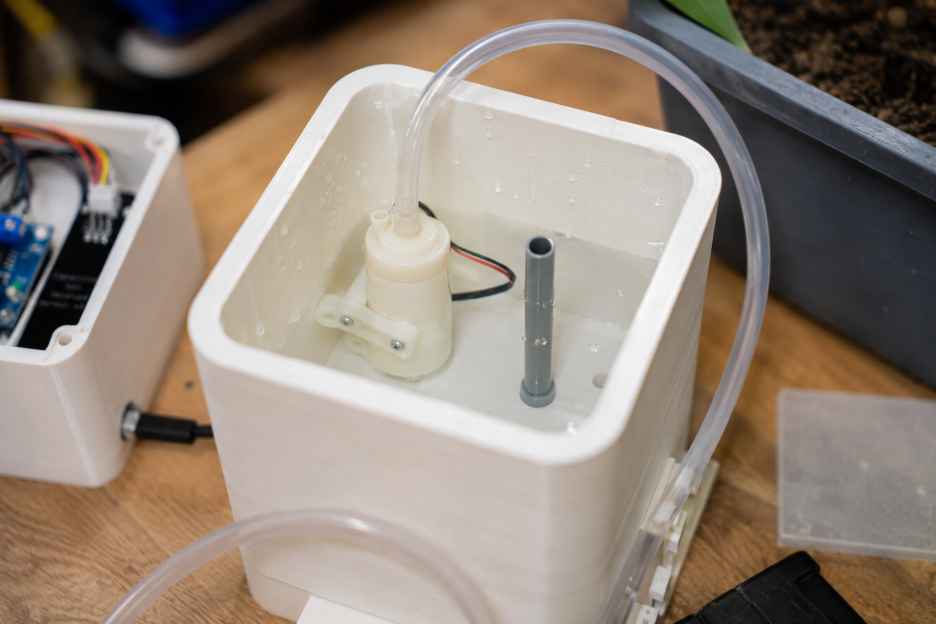
Step 2: Install the pump in the reservoir
Fix the mini water pump inside the bottom reservoir using the printed bracket. Connect the silicone tube to the pump outlet and route the tube upward into the planter section through the tube guide.
.png)
Step 3: Mount the moisture sensor
Insert the capacitive soil moisture sensor into the printed holder and place it inside the planter soil area. The sensor should sit deep enough to sense moisture consistently but should not touch the water reservoir directly.
.png)
Step 4: Assemble the control enclosure
Mount the ESP32, relay module or MOSFET driver, and status LED inside the side enclosure. Bring out the wires for the sensor, pump, and power input through small side openings.
.png)
Step 5: Complete the wiring
Connect the moisture sensor output to one of the ESP32 ADC pins. Connect the relay input or MOSFET gate to a digital output pin of the ESP32, and connect the pump through the driver circuit to the power supply, which matches the standard automatic pump-control arrangement used in ESP32 watering setups.
.png)
Step 6: Upload the program
Upload the Arduino IDE code to the ESP32. Open Serial Monitor and observe the moisture readings so the dry and wet values can be identified for calibration, which is an important setup step for this kind of sensor-based watering system.
Arduino IDE Download | ESP32 Board Manager Setup
Step 7: Test the watering cycle
Fill the reservoir, place the plant in the pot, and allow the soil to dry slightly. Once the sensor value crosses the dry threshold, the ESP32 should activate the pump and water the plant for the programmed duration.
Calibration
Capacitive soil moisture sensors need calibration because the analog reading changes with sensor type, soil type, and placement depth. The usual method is to first read the sensor value in dry soil, then read it again in wet soil, and choose a threshold value between the two conditions.
This threshold is then updated in the code. Proper calibration is important because an incorrect threshold can either overwater the plant or delay watering too much.
Possible Improvements
A status OLED can be added to display moisture percentage and pump status. Wi-Fi features can also be added later so the planter can send notifications or show readings on a simple web dashboard, since ESP32 supports connected monitoring in addition to basic local control.
Another useful improvement is a float switch or water-level sensor in the reservoir so the pump does not run dry. This makes the planter more reliable for long unattended use.
Code & Downloads
#define SOIL_SENSOR_PIN 34

#define PUMP_PIN 26

#define LED_PIN 2


const int DRY_THRESHOLD = 2500;

const int WET_THRESHOLD = 1400;

const unsigned long PUMP_ON_TIME = 4000;

const unsigned long CHECK_INTERVAL = 10000;

const unsigned long POST_WATER_DELAY = 30000;


unsigned long lastCheckTime = 0;

unsigned long lastWaterTime = 0;

bool pumpState = false;


void setup() {

  Serial.begin(115200);

  pinMode(PUMP_PIN, OUTPUT);

  pinMode(LED_PIN, OUTPUT);

  digitalWrite(PUMP_PIN, LOW);

  digitalWrite(LED_PIN, LOW);

}


void loop() {

  unsigned long currentTime = millis();


  if (currentTime - lastCheckTime >= CHECK_INTERVAL) {

    lastCheckTime = currentTime;


    int moistureValue = analogRead(SOIL_SENSOR_PIN);

    Serial.print("Moisture Raw Value: ");

    Serial.println(moistureValue);


    int moisturePercent = map(moistureValue, DRY_THRESHOLD, WET_THRESHOLD, 0, 100);

    moisturePercent = constrain(moisturePercent, 0, 100);


    Serial.print("Moisture Percentage: ");

    Serial.print(moisturePercent);

    Serial.println("%");


    if (moistureValue >= DRY_THRESHOLD && (currentTime - lastWaterTime >= POST_WATER_DELAY)) {

      waterPlant();

      lastWaterTime = millis();

    } else {

      digitalWrite(LED_PIN, LOW);

      digitalWrite(PUMP_PIN, LOW);

      pumpState = false;

    }

  }

}


void waterPlant() {

  Serial.println("Soil is dry. Turning pump ON.");

  digitalWrite(LED_PIN, HIGH);

  digitalWrite(PUMP_PIN, HIGH);

  pumpState = true;


  delay(PUMP_ON_TIME);


  digitalWrite(PUMP_PIN, LOW);

  digitalWrite(LED_PIN, LOW);

  pumpState = false;

  Serial.println("Watering complete. Pump OFF.");

}