
OPERATION OF THE CIRCUIT
This system aims to help farmers switch on/off the pumps used for irrigation remotely using DTMF signals .
The pre - requisites for this system to work :-
1. Availability of electricity
2. A mobile phone
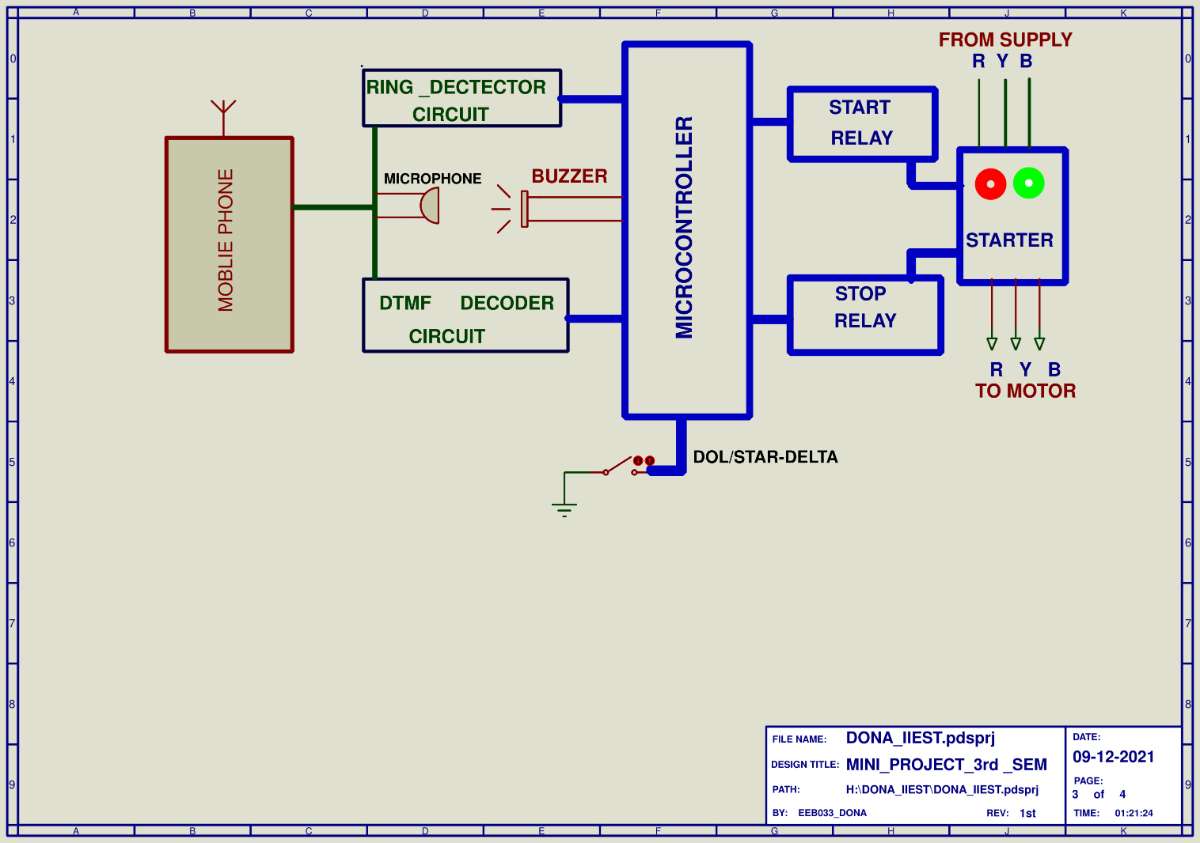
A mobile phone is interfaced to the input of a DTMF decoder circuit and Ring detector circuit through an earphone . When the user calls on the receiving end mobile , the Ring detector circuit detects the DTMF tone. It then send this information to the microcontroller which after confirming the ring tone instructs the call relay (part of the RING detector circuit ) to receive the call . After the call has been received the user needs to dial a particular sequence of numbers for starting and stopping the pump . When these digits are dialed , there is a beep after every digit to give indication to the user that the circuit has received the digit he/she has dialed . After receiving DTMF signals (the digits are having 2 frequency corresponding to each one ; this method of transferring signals is called DTMF) , the DTMF decoder circuit . The received DTMF signals are decoded to 4 bit binary digits by the DTMF decoder circuit. These 4 bit sequences are then fed to the microcontroller. Identifying the number sequences that have been sent from the sender’s mobile , the microcontroller gives instructions as to switch on / off the relay switches .
As due to the current Protocols , most mobiles now-a-days don’t have the option to be put on “auto - receiving / ride” mode to avoid accidents , we needed to include the Ring - detector circuit which detects the tone when the mobile rings and in turn feeds this information to the microcontroller which further confirms it and instructs the call relay ( part of the ring detector circuit ) to receive the call . This actually is a complementary mechanism to overcome the issue of the unavailability of auto - receiving mechanism .
- Dial Number 1 4 7 for Pump on and 7 4 1 for Pump off for Star/Delta Motor.
- Dial Number 3 6 9 for Pump on and 9 6 3 for Pump off for DOL Motor .
BLOCK DIAGRAM OF THE CIRCUIT
CIRCUIT DIAGRAMS
- RING DETECTOR CIRCUIT
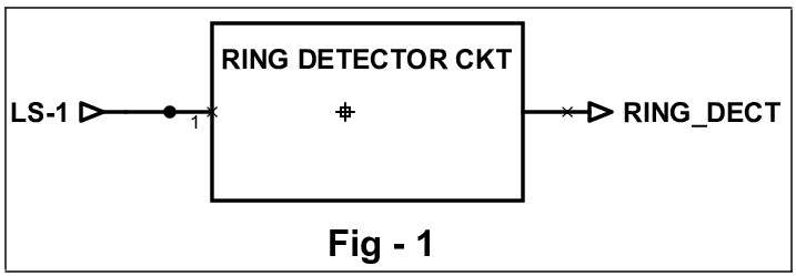
One terminal of the speaker (LS-1) serves as the input to the ring detector circuit through which it receives the ringtone when the phone rings . The output (here mentioned as RING_DECT) of this circuit is connected as input to the pin D4 of the microcontroller .
2. CALL RELAY ( PART OF RING DETECTOR CIRCUIT )
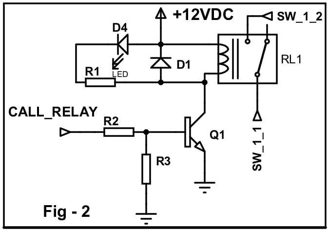
Once the microcontroller confirms the ring , the call relay receives instruction and in turn switches on the relay (RL1) which is indicated by a momentary glowing up of the LED D4 in the above circuit . This does the function of auto - receiving the call.
3. EARPHONE + BUZZER
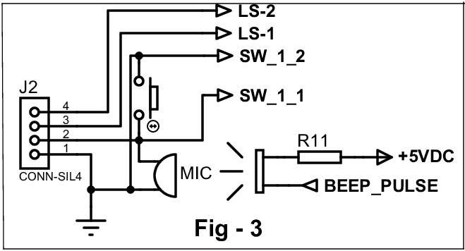
The microphone , LS1 and LS2 (two terminals of the left and right speakers) - all belong to the earphone being used to connect the receiving mobile to the circuit . When the receiving mobile receives numbers entered by the user , the circuit gives a beep pulse to help the user understand that the circuit received a number .
4. DTMF DECODER
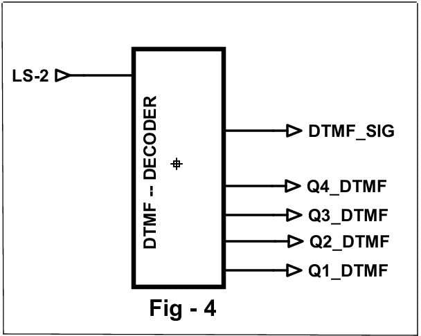
The DTMF decoder circuit has one terminal of the speaker connected to it’s input through which it receives the DTMF signals . In the circuit , the signals are decoded into 4- bit binary sequences (here , Q1,Q2,Q3,Q4 ) . Once a signal is decoded , this circuit sends a STG signal (here DTMF_SIG) to the interrupt pin of the microcontroller to indicate that a new data has arrived which is to be read .
5. MICROCONTROLLER
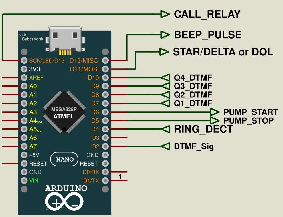
This ( ATMEGA 328 microcontroller ) works as the “brain” of this circuit . It reads the information as received by the receiving mobile and works according to the instructions already programmed in it and in turn switches the pump motor on/off either in Star-Delta mode or DOL mode .
6. STARTING OF THE PUMP
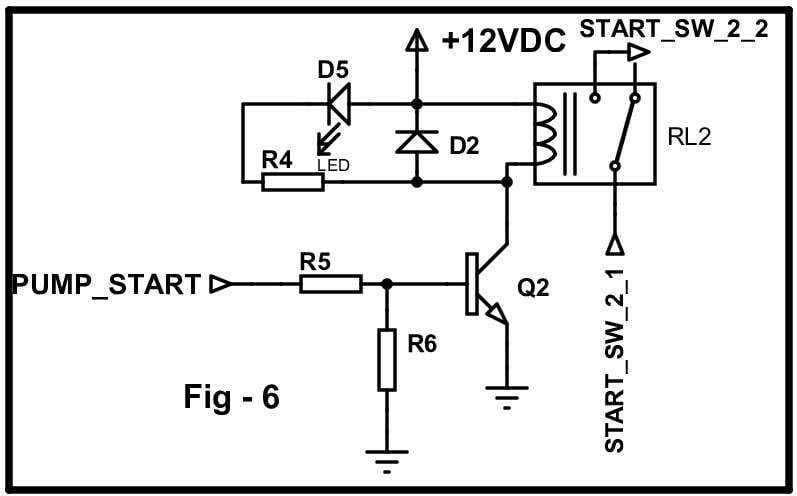
Once the proper set of numbers (for switching on) are entered, the microcontroller pin D6(PUMP_START) will be high and hence the start relay (RL2 shown in fig.6) will be on .
7. SWITCHING OFF THE PUMP
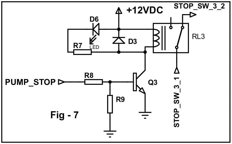
Once the proper set of numbers (for switching off) are entered, the microcontroller pin D5(PUMP_STOP) will be high and hence the stop relay (RL3 shown in fig.7) will be on . This will switch off the pump motor .
8. POWER SUPPLY OF THE CIRCUIT
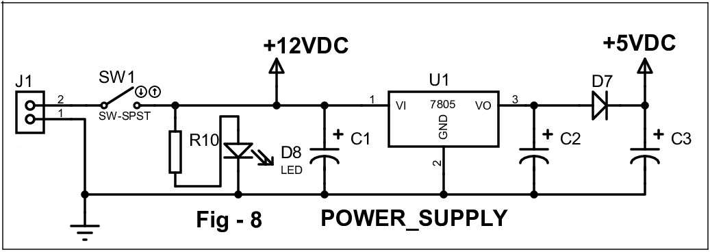
All the three relays of the circuit receive voltage from the 12V DC source and all the other parts of the circuit including the microcontroller receive voltage from the 5V DC source as shown in Fig.8 .