
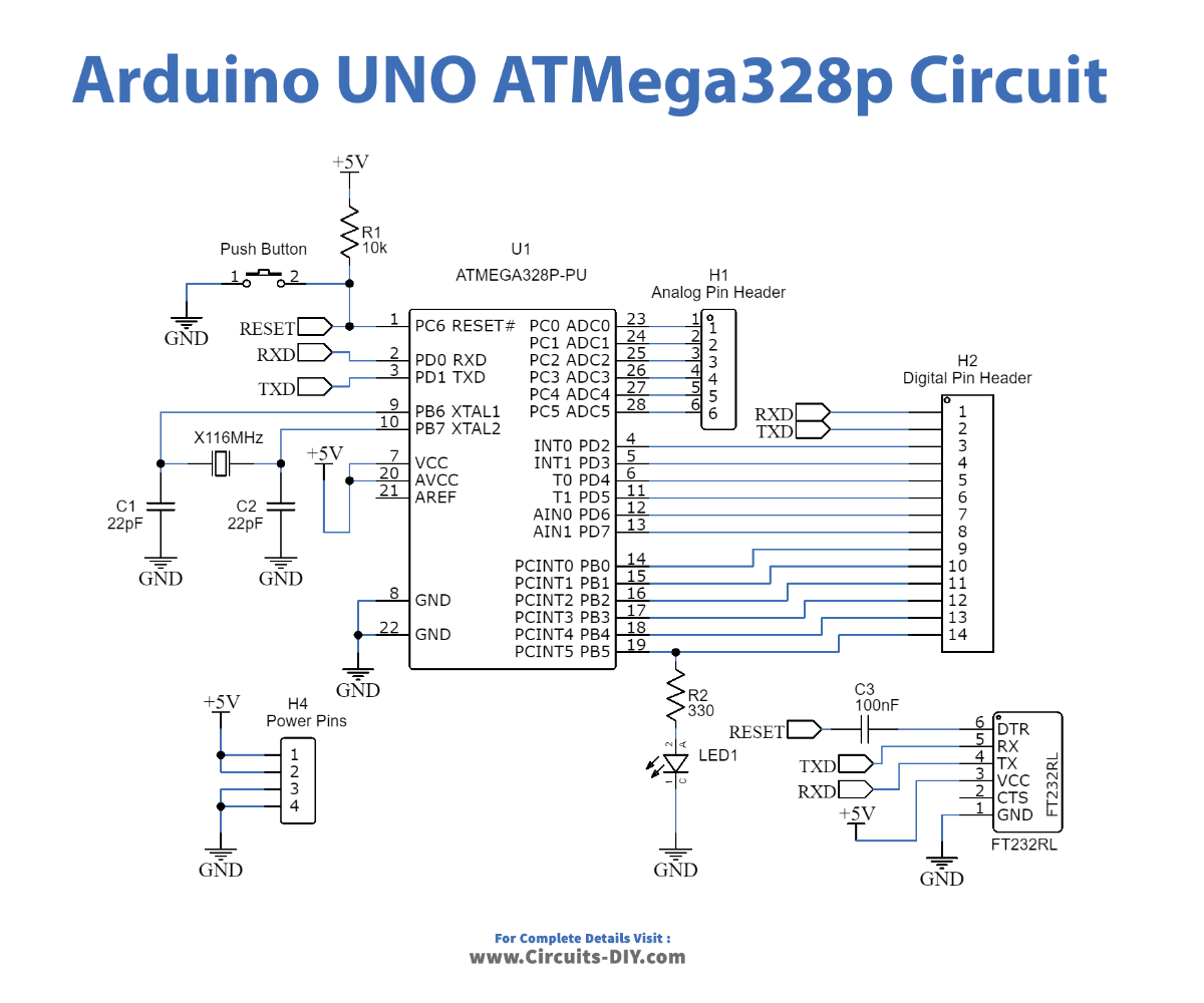
The Arduino uses the ATMega328p chip. We can get that in an SMD format (ATMega328p-AU) or the DIP format for trough hole soldering (ATMega328p-PU). But, the chip by itself can't work. It needs a few more components and altogether is called the bare minimum configuration of this chip. So In this tutorial, we are going to design our own custom-made "Arduino UNO PCB" using an ATMega328p chip.
PCBWay commits to meeting the needs of its customers from different industries in terms of quality, delivery, cost-effectiveness, and any other demanding requests. As one of the most experienced PCB manufacturers in China. They pride themselves to be your best business partners as well as good friends in every aspect of your PCB needs.
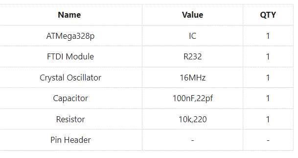
Hardware Table
Upload a Test code
Before Uploading a test code you first need to Install FTDI Module Drivers. Download FTDI 232 Driver and Install It according to your operating system.
Now, we have the bootloader so we can communicate with the RX and TX pins and upload a code. For that, we need an FTDI module. Make the next connections and Upload this code to our designed Arduino board. If LED is blinking so it means you have successfully designed your own custom Arduino board.
Test Code
void setup() {
  // initialize digital pin LED_BUILTIN as an output.
  pinMode(LED_BUILTIN, OUTPUT);
}


void loop() {
  digitalWrite(LED_BUILTIN, HIGH);   // turn the LED on (HIGH is the voltage level)
  delay(1000);                       // wait for a second
  digitalWrite(LED_BUILTIN, LOW);    // turn the LED off by making the voltage LOW
  delay(1000);                       // wait for a second
}