
Introduction & The Problem
Every year, two-wheeler accidents claim over 75,000 lives across India. Statistically, more than 70% of these tragic fatalities are directly linked to non-compliance—either the rider completely refused to wear a helmet, or they chose to operate the vehicle under the influence of alcohol. Even when an accident occurs, the critical "Golden Hour" is frequently lost because injured or unconscious riders are physically incapable of calling for emergency assistance.
Current market accessories fail drastically here. Standard "smart" helmets use basic IR (Infrared) proximity sensors to detect a head, which riders easily bypass by buckling the helmet over the petrol tank or across the seat. Furthermore, standard accident systems rely on primitive vibration sensors or simple binary threshold spikes. These lack dynamic logic, meaning a standard Indian pothole or a harsh speed bump triggers a false emergency broadcast.
Our project completely re-engineers this paradigm. By building an IoT-driven dual-node enforcement framework combined with an on-device Edge AI classifier, we ensure that vehicle ignition is physically locked unless a human rider is legitimately wearing the helmet sober, and that emergency teams receive instant GPS data only when a real accident occurs.
System Architecture & Wireless Workflow
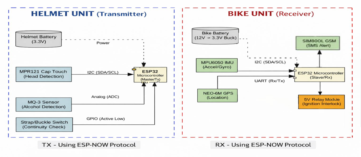
To isolate sensing environments from the vehicle's high-vibration chassis, we decoupled the design into a dual-node master-slave layout. Instead of relying on unreliable, slow Bluetooth pairing or external Wi-Fi networks, the nodes communicate over a raw, low-latency ESP-NOW wireless protocol.
1. The Helmet Node (Transmitter)
The helmet functions as the primary safety validator, collecting and processing human parameters before any trip begins:
- True Head Detection (Anti-Cheating): We bypassed fragile IR sensors completely. Instead, we integrated an MPR121 Capacitive Touch Sensor Controller mapped to a customized copper foil pad array inside the helmet lining. It measures actual capacitance changes from human skin contact. If a rider attempts to stick a bag or strap in the helmet, the capacitance delta fails to validate, instantly locking out the system.
- Sobriety Screening: An MQ-3 Alcohol Gas Sensor is positioned directly in front of the rider's breath path. Before engine ignition is cleared, the system samples the air. If alcohol PPM readings cross our calibrated safety threshold, the validation routine aborts.
- Brain & Transmission: An ESP32 Microcontroller handles the local interrupts, packages the sensor states, and fires low-overhead ESP-NOW data packets across the 2.4GHz band every few milliseconds.
2. The Bike Node (Receiver)
The bike unit acts as the physical enforcement and emergency communication hub:
- Ignition Interlock: A second ESP32 Microcontroller listens for the incoming ESP-NOW packets. The digital ignition circuit of the motorcycle passes directly through a 5V Active-Low Relay Module. If the helmet node reports "Not Worn" or "Alcohol Detected," the microcontroller keeps the relay contacts open, physically disabling the starter motor.
- Environmental Tracking: An MPU6050 6-Axis Inertial Measurement Unit (IMU) is rigidly mounted to the vehicle frame to track real-time linear acceleration and angular velocity ($X, Y, Z$ axes).
- Emergency Broadcast: The node interfaces via hardware UART with a NEO-6M GPS Module for continuous NMEA coordinate parsing and a SIM800L GSM Module for cellular connectivity.
.jpeg)
TinyML Crash Classification via Edge Impulse
To completely eliminate false alarms caused by rough roads, we moved away from simple threshold programming and deployed an on-device Machine Learning classifier.
1. Data Acquisition & Dynamic Scenarios
We rigged our prototype and manually collected extensive time-series IMU datasets across multiple distinct real-world scenarios to teach our model the difference between normal driving anomalies and a genuine crisis:
- IDEAL: Standard, clean riding accelerations.
- POTHOLE: Harsh vertical shocks and sudden impacts from broken roads.
- LEFT / RIGHT DRAG: Sliding anomalies and skids.
- LEFT / RIGHT ACCIDENT: True high-impact structural drops and orientation roll-overs.
2. The Machine Learning Pipeline
Using Edge Impulse, we structured a comprehensive TinyML pipeline to extract hidden features within our dataset:
- Spectral Analysis Block: This block filters raw, noisy 6-axis data from the MPU6050. It applies a fast Fourier transform (FFT) to extract power spectral density across the frequency domain, converting raw spatial motion into crisp statistical features.
- Neural Network Classifier Block: A multi-layer dense neural network was trained on these spectral features.

3. Validation Results
The model achieved an exceptional 99.8% validation accuracy during training. As verified by the confusion matrix, the network successfully classifies a severe "Pothole" impact as non-hazardous, while immediately identifying a true "Right Drag" or "Left Accident" based on the complex interplay of angular rotation and structural deceleration. The final model was compiled using the EON Compiler to optimize memory utilization, allowing the entire neural network to execute locally on the ESP32 chip within milliseconds.

Step-by-Step Hardware Build & Implementation
Building the prototype requires clean execution across both independent power domains:
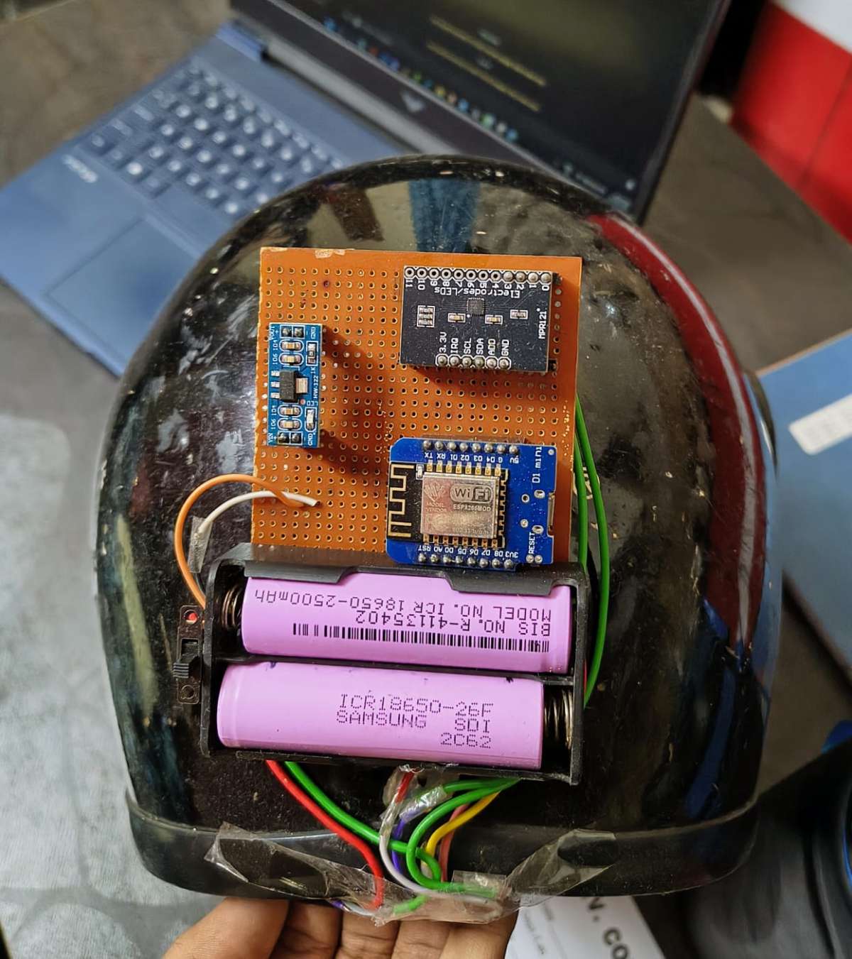
Step 1: Assembling the Helmet Array
- Line the inner safety foam of the helmet with thin, conductive copper foil strips, ensuring they sit flush against the areas that tightly contact the rider's scalp.
- Route the foil leads to the input channels of the MPR121 breakout board via short, shielded wires to mitigate parasitic environmental capacitance.
- Secure the MQ-3 sensor near the chin bar using a 3D-printed enclosure, ensuring its exhaust vents are clear.
- Wire the sensors to the primary ESP32 (Tx Node) and power the entire helmet circuit cleanly using a regulated 3.7V 18650 Li-ion battery.
Step 2: Wiring the Bike Interlock Node
- Mount the MPU6050 IMU dead-center on your test chassis. It must be perfectly parallel to the vehicle's axis of travel to avoid skewing the TinyML spatial features.
- Connect the NEO-6M GPS to the ESP32’s hardware serial pins (
RX2/TX2). - Interface the SIM800L GSM module. Critical Design Note: The SIM800L requires brief current bursts up to 2A during cellular handshakes. Power it through an adjustable high-current buck converter stepped down to 4.2V, rather than running it directly from the ESP32's internal regulators.
- Splice the vehicle's ignition/starter wire through the common and normally-open (NO) contacts of the 5V active-low relay, linking the relay's control pin to a designated GPIO on the ESP32 (Rx Node).
DEMONSTRATION VIDEO