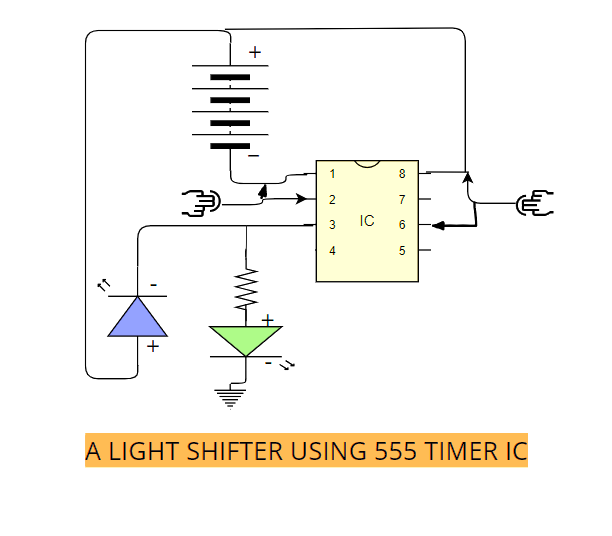
A LIGHT SHIFTER USING 555 TIMER IC
Description:- We can certainly use a 555 timer IC to to make this project.
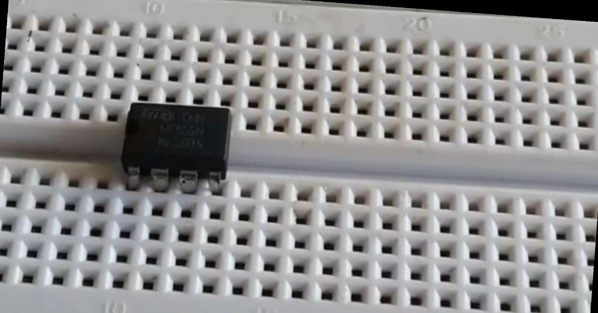
An easy-to-make project.Essentially we need a breadboard if not a zero pcb.But make sure to connect the wires carefully in order to prevent the current leakage which may interfere with normal working of this project.
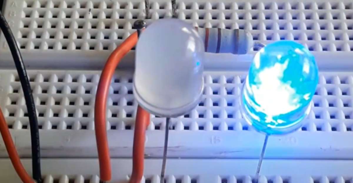
- A 555 timer IC consisting 8 pins is apt for making it.LEDs are required to be connected with desired polarity in order to prevent fuse.
- A 330 ohm register can be used which you may identify by looking at the color combination of the resistor body. It consists of golden tolerance band and 2 orange plus one brown band.
- The first two bands indicate the resistance value and the third band serves as a multiplier.
Colour code chart
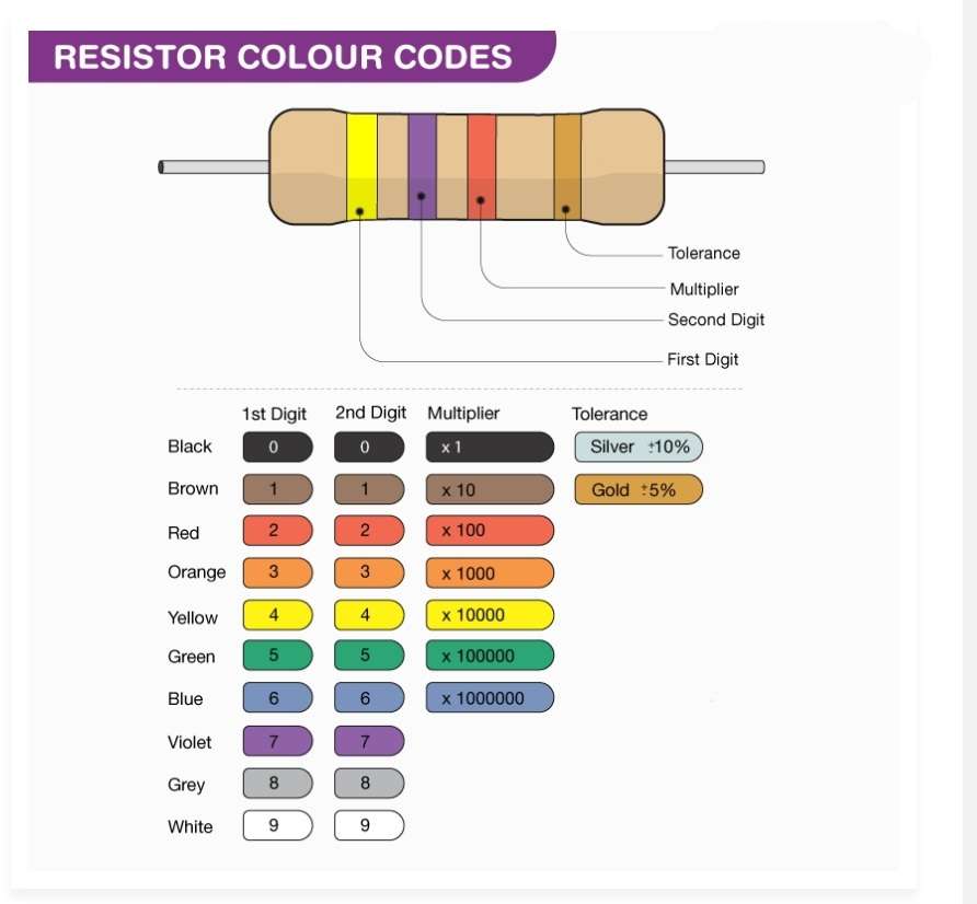
Resistors are normally tiny, and it is cumbersome to print resistor values on them. So, colour bands are printed on them to represent the electrical resistance.
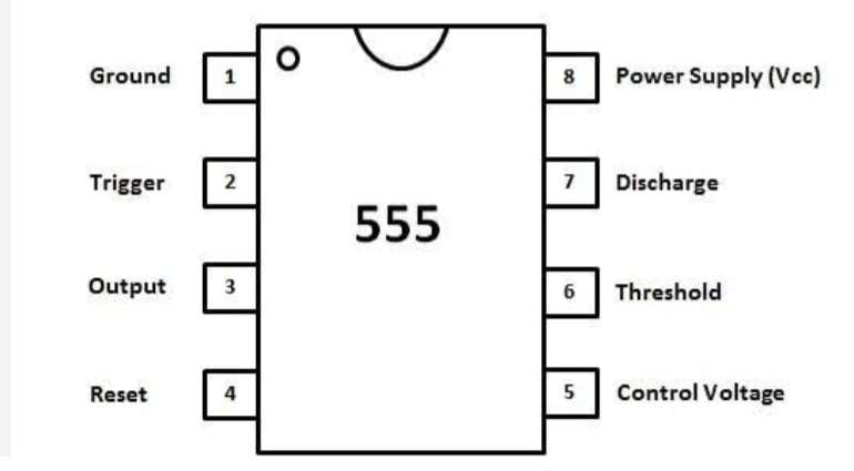
A 555 timer IC
•••••••••••••••••••••••••••••••••••••
It works by touching both pins of one side simultaneously. It will complete the circuit and the colour of the LEDs will then shift.
Points to be noted while making connections:-
- Always remember that there is a chance of current leakage if one uses breadboard. Prefer a zero pcb and make permanent connections.
- Technically speaking , an LED is one of the most delicate components. It fuses immediately due to mishandling or giving it improper voltage.
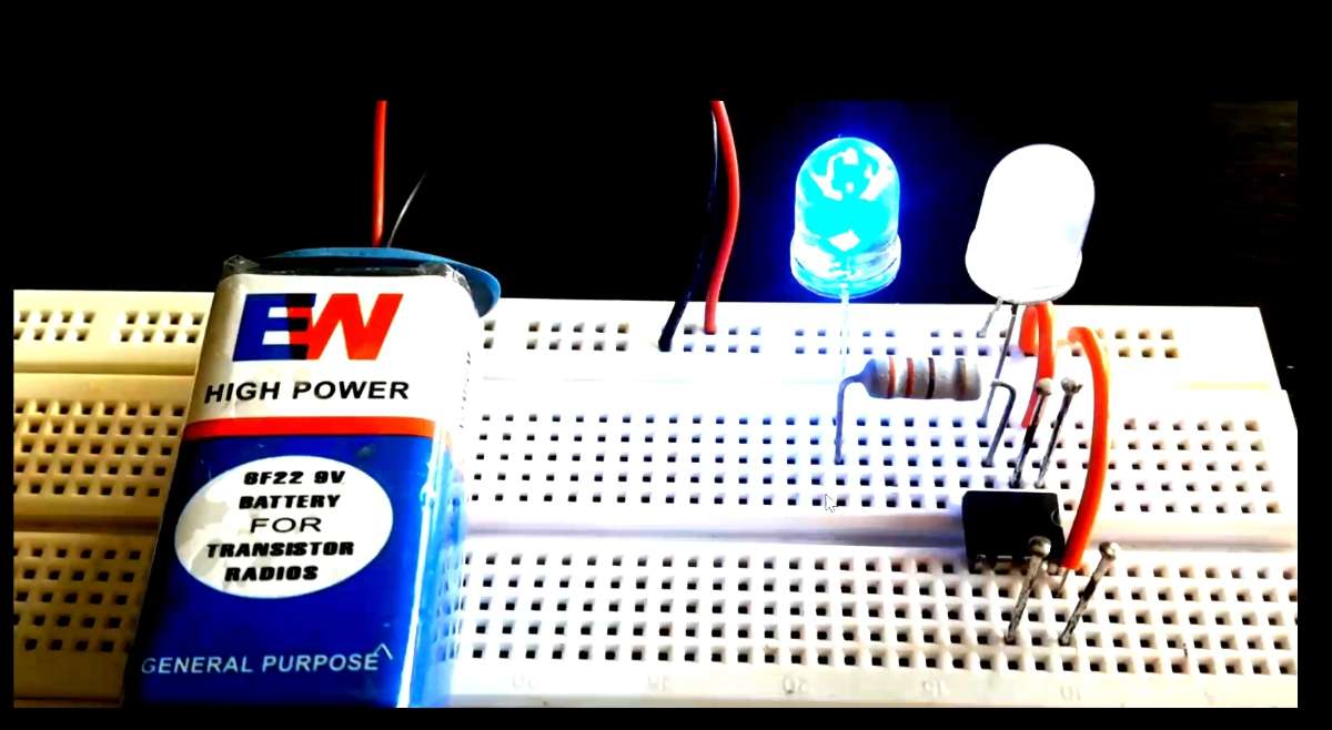
Photos of components and connection:-
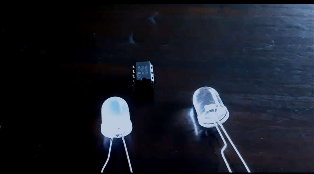
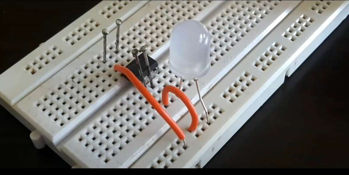
- Project/Model ready->>
- Circuit Diagram ->>
Those who are interested in knowing this project detail they may visit the project video page by clicking the link below.
I would like to thank Electronic Wings and DigiKey both for providing me opportunity to showcase my hidden talent and skills.