Animatronic Human like Home assistant skully
By Archit Jain
Technology today is rapidly transforming the way humans interact with machines, making systems more intuitive, lifelike, and intelligent. Advancements in Artificial Intelligence (AI), robotics, and embedded systems have opened new pathways for creating machines that can mimic human expression and behaviour. This project, “AI-Driven Animatronic Face with Eye Tracking, Speech Generation, and Realistic Motion,” integrates these modern technologies to build a robotic face capable of natural interaction through movement, vision, and conversation.
In the modern world, robots are shifting from purely functional machines to interactive systems that can communicate and collaborate with humans. Whether in education, healthcare, entertainment, or research, human-like robots can make interactions more natural and engaging. Animatronic faces, in particular, help bridge the communication gap by providing visual expressiveness and emotional clarity.
Key Features of the Project
- Jaw movement synchronized with speech
- Neck movement for natural head gestures
- Modular 3D-printed components
- Custom servo-driven mechanics
Such systems can be used for:
- Educational demonstrations
- Human–robot interaction research
- Entertainment and animatronics
- Assistive communication tools
- Creative AI-powered installations
Components Required
| Component Name | Quantity | Datasheet/Link |
| ESP32 Devkit V1 | 1 | - |
| PCA9685 | 1 | - |
| MG90s Servos | 6 | - |
| MG995 Servos | 4 | - |
| Adafruit Memento Camera Board | 1 | - |
| 3d Printed Parts | 25 | - |
| Capacitors(1000uf) | 5 | - |
| SMPS power supply (5v 10amps) | 1 | - |
| Speaker | 1 | - |
| Microphone | 1 | - |
| rasberry-pi 4 or a laptop | 1 | - |
3D Printing Material Selection
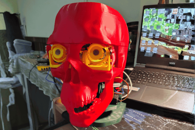
All mechanical components were manufactured using a Bambu Lab P1S 3D printer ( Fig 3.1), with PLA filament, chosen for its dimensional stability, low weight, and ease of printing. The goal was to produce lightweight, structurally rigid parts suitable for servo-driven mechanisms. PLA’s balance of strength and print quality made it ideal for the skull, linkage components, and servo mounts.
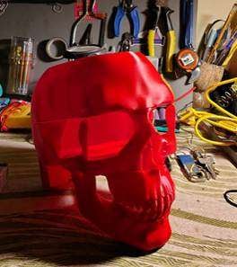
Fig : Bambu Lab P1S
Slicing & Printer Settings
To optimize print speed and reduce weight, most parts were printed with 5% sparse infill, supported by various infill patterns such as gyroid, honeycomb, triangle, and others as appropriate to each part's load distribution. A 2-line outer brim was added to ensure adhesion and dimensional accuracy. Supports were used selectively: some components required tree supports for overhangs, while others used standard supports based on the geometry and required surface finish. These tailored slicing choices ensured smooth mechanical motion and reduced unnecessary mass.
.png)
Fig: Printing of Slice Plate
Mechanical Assembly Procedure
The assembly involved multiple screw sizes and types to secure the mechanisms and structural components. The eye mechanism was mounted inside the upper cranium, ensuring alignment with the facial opening. The jaw mechanism was fixed to the main skull using two M4 bolts, providing a strong hinge foundation for speech-style movement. After assembling the skull sections, the entire head structure was mounted onto the neck mechanism, completing the mechanical chain. Each subsystem was tested during assembly to confirm servo clearance, linkage freedom, and smooth articulation.
.png)
Fig: Final Mechanical Assembly
Modelling
Eye Mechanism
The eye mechanism is inspired by Will Cogley’s high-precision animatronic design, adapted to suit lightweight materials and compact mounting requirements. The system uses a total of six SG90 micro servos, Refer to (Fig 3.4) two for controlling the upper eyelids, two for the lower eyelids, one for eyeball tilt, and one for eyeball pan. This configuration enables expressive, human-like movements with independent eyelid control and smooth ocular tracking. The internal linkage system is optimized to ensure minimal backlash and consistent motion during rapid directional changes.
Fig: CAD and Printed model of Eye Mechanism
Jaw Mechanism
The jaw mechanism operates using a single MG995 high-torque servo, selected for its strength and stability under repetitive load cycles. The servo drives a hinge-based lower jaw that follows natural human jaw motion, providing realistic opening angles suitable for synchronized speech animation with the TTS pipeline. The mechanism is structurally reinforced to maintain alignment while minimizing vibration during fast movements.
Fig : CAD and Printed model of Jaw Mechanism
Skull & Facial Structure
The outer skull is modelled based on human anatomical proportions, providing natural contours and realistic facial geometry. The design accommodates internal mounting points for servos, wiring channels, and mechanical linkages without compromising aesthetic structure. The 3D-printed shell s segmented for easy assembly and maintenance while still maintaining sufficient rigidity to support the eye, jaw, and neck mechanisms.
Neck Mechanism (3-DOF)
The neck system provides three degrees of freedom using two servos for tilt control (pitch movement) and one servo for rotational movement (yaw). The dual-tilt arrangement distributes mechanical load and enables smoother, more controlled forward/backward and sideways bending. The central rotation servo provides the base for head turning. All three actuators are mounted in a stacked configuration with a hollow internal channel for cable routing, ensuring clean movement without wire interference.
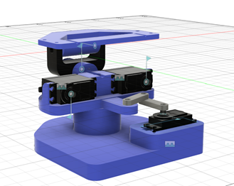
Fig: CAD Model of Neck Mechanism
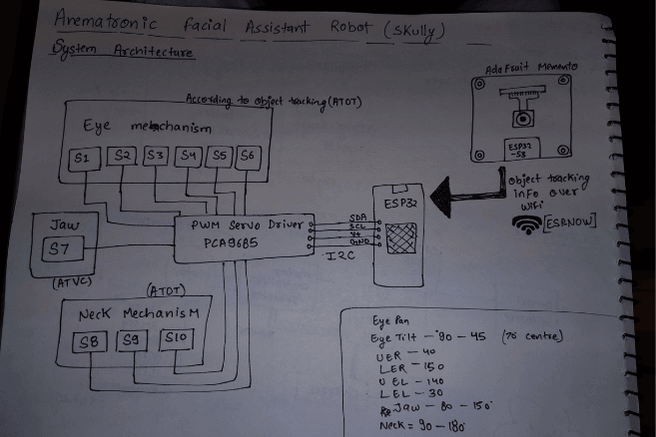
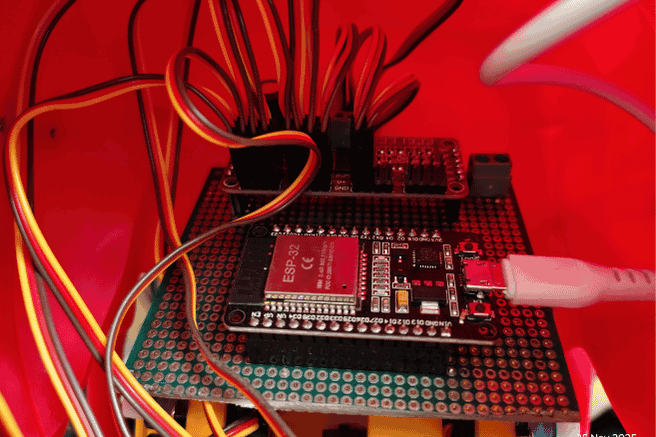
Circuit Diagram
POWER DISTRIBUTION
- External Servo Supply
- - 5V 10A SMPS
- - GND tied to ESP32 GND
PCA9685
- VCC → ESP32 3.3V
- V+ → 5V (Servo Power)
- GND → Common Ground
I2C BUS
- ESP32 (Main):
- GPIO 21 → PCA SDA
- GPIO 22 → PCA SCL
- 3.3V → PCA VCC
- GND → PCA GND
SERVO CONNECTIONS
PCA9685 Channels:
- EYE MECHANISM (ATOT)
- CH0 → S1 (Eye Pan)
- CH1 → S2 (Eye Tilt)
- CH2 → S3 (Upper Eyelid Right)
- CH3 → S4 (Lower Eyelid Right)
- CH4 → S5 (Upper Eyelid Left)
- CH5 → S6 (Lower Eyelid Left)
- NECK MECHANISM (ATOT)
- CH7 → S7 (Neck Tilt)
- CH8 → S8 (Neck Tilt)
- CH9 → S9 (Neck Roll)
- JAW (ATVS)
- CH11 → S10 (Jaw Open/Close)
JAW SYNC INPUT (USB SERIAL)
- Laptop / Raspberry Pi → ESP32 over USB
- USB TX → ESP32 RX0 (UART0)
- USB RX → ESP32 TX0 (UART0)
- USB GND → ESP32 GND
OBJECT TRACKING NODE
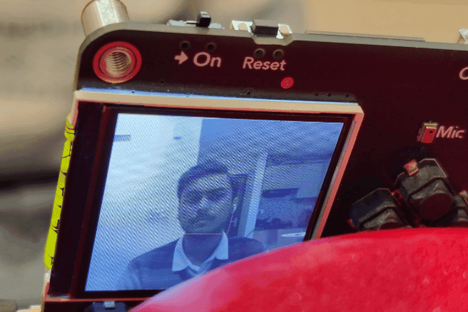
- Adafruit Memento ESP32-S3 CAM:
- OV2640 Camera
- Runs tracking model
- Sends (x,y) tracking info via ESP-NOW
Hardware Assembly
1. Mechanical Assembly
All the 3D-printed parts of the robot were first aligned and assembled using screws. Each moving section—eyes, neck, and jaw—was mounted securely so the mechanisms were stable and ready for electronics installation.
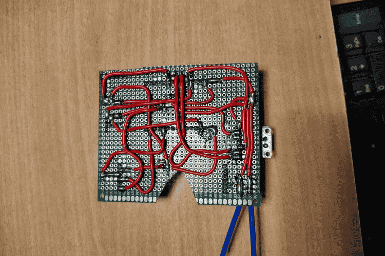
 2. Electronics Installation
Once the mechanical assembly was complete, the circuit components were plugged in. This included connecting the ESP32, the servo controller board, and all the servos to their designated ports according to the design.
 3. Hardware Testing
After everything was connected, all the test codes inside the test directory were run. These tests helped verify that each servo was functioning properly and that every mechanism could move through its expected range without issues.
4. Servo Calibration
Each servo was calibrated one by one. This involved checking its movement limits, adjusting the angles to avoid mechanical strain, and confirming smooth motion. Eye servos, neck servos, and the jaw servo were all individually calibrated to ensure accurate responses later in the system.
5. Camera Integration
Once calibration was complete, the ESP32-CAM board was mounted on the robot’s forehead. The face-tracking code was then uploaded, enabling the camera to detect a person’s face and send tracking information to the main ESP32.
 6. Eye Tracking Mapping
The main ESP32 received the tracking data from the camera and passed it to the servo controller. The controller mapped this data to the eye servos so the robot could follow the user’s face with smooth eye movement.
7. Audio System Setup
Finally, the speaker and microphone were installed. These components allowed the robot to listen and respond, enabling the voice assistant functionality to work alongside the animatronic movements.
Code Explanation
Project Structure
Animatronic-Facial-Assistant-with-Vision-Guided-Eye-and-Jaw-Movements/
doc/ # Reference documents & servo limit charts
├── Eye Tracking/ # Vision-based eye tracking models & scripts
├── Face Tracking/ # ESP32/PlatformIO projects for head/face tracking
├── src/ # Main code: LLM agent + servo controller node
├── test/ # Hardware test sketches for servos/animations
├── LICENSE # License information
└── README.md # This documentation
System Architecture
Camera -->|Frames| EyeTracking[Eye Tracking (DNN / Haar)] EyeTracking -->|Eye position| ServoESP[ESP32 Servo Controller]
Camera2 -->|Frames| FaceTracker[Face Tracking Node] FaceTracker -->|Coordinates| ServoESP
Mic --> STT[Speech-to-Text (Vosk)] STT --> LLM[LLM Voice Agent (Groq / Python)] LLM --> TTS[Text-to-Speech Engine] TTS --> Speaker
LLM -->|Commands| ServoESP ServoESP --> Hardware[Servos: Eye, Jaw, Neck]
## Setup Instructions
### 1. Clone the repository
``` bash
git clone [email protected]:YOUR_USERNAME/Animatronic-Facial-Assistant-with-Vision-Guided-Eye-and-Jaw-Movements.git
cd Animatronic-Facial-Assistant-with-Vision-Guided-Eye-and-Jaw-Movements
Face Tracking (ESP32)
Build & upload:
cd Face\Tracking/Platformio_memento_camera_node
pio run --target upload
This program turns the Adafruit MEMENTO (ESP32-S3) into a real-time face-tracking camera that also sends face coordinates wirelessly.
What it does
1.Uses the onboard camera to capture frames.
2.Runs AI-based face detection on each frame.
3.Draws a face box + center dot on the 240×240 ST7789 display.
4.Sends the face’s x/y position, width, height, and timestamp via ESP-NOW to another ESP32.
5.Repeats this continuously for live face tracking.
Libraries Used
Camera & AI
- esp_camera.h → controls the camera hardware
- human_face_detect_msr01.hpp → first-stage face detector
- human_face_detect_mnp01.hpp → second-stage refinement
- face_recognition_112_v1_s8.hpp → face recognition model (loaded but not actively used)
- face_recognition_tool.hpp → helper tools for detection & recognition
Display / Graphics
- Adafruit_GFX.h → base graphics library
- Adafruit_ST7789.h → driver for the 240×240 TFT
- fb_gfx.h → frame buffer utilities
Wireless Communication
- esp_now.h → ESP-NOW fast P2P communication
- WiFi.h → needed because ESP-NOW uses WiFi hardware
Utilities
- TJpg_Decoder.h → JPEG decoding (for other features)
- SPI.h, Wire.h → communication buses
- <vector> → C++ vector container
- ra_filter.h → smoothing/filtering utility
Main Program Flow
1.Initialize Camera
2.Sets camera pins, resolution, color format, PSRAM framebuffers, etc.
3.Initialize Display
4.Turns on/wakes the ST7789 screen and prepares it for drawing.
5.Initialize ESP-NOW
6.Sets the board as WiFi station, configures peer MAC, and enables send callbacks.
7.Loop:
- Grab current camera frame
- Run face detection models
- If face exists:
- Draw a green rectangle and a blue midpoint
- Fill the faceData struct
- If not: mark face as missing
- Send data via ESP-NOW
- Byte-swap frame to match the display format
- Draw the camera image on the TFT
- Return the frame buffer
LLM Voice Agent Node
Create virtual environment:
cd src/LLM_voice_Agent_node
python3 -m venv virEnv
source virEnv/bin/activate
pip install -r requirements.txt
Run:
python3 main.py
Explanation of the Program
This script creates a voice-controlled robot personality ("Skully") that can:
- Listen to your speech using a microphone
- Convert speech → text using Vosk
- Send the text to an AI model (Groq LLaMA-3.1)
- Get a short, friendly AI reply
- Speak the reply aloud using Piper TTS
- Move a robotic jaw in sync with the speech through a serial connection
Everything runs in a continuous loop and feels like talking to a character.
Libraries Used
Speech-to-Text (STT)
- vosk → offline local speech recognition
- sounddevice → captures live microphone audio
- numpy → audio array operations
AI Chat
- groq → sends messages to Groq’s LLaMA-based chatbot model
Text-to-Speech (TTS)
- piper → lightweight, fast ONNX neural voice
- slows playback slightly to match jaw animation
Robot Jaw Control
- serial → communicates with an ESP32/Arduino
- sends simple commands: "JAW_START", "JAW_STOP"
System / Utilities
- dotenv → loads API key from .env
- json, time, threading, queue, os → support logic
ESP32 Servo Controller Node
Upload:
pio run --target upload
This program runs on an ESP32 and controls a full animatronic head: eyes, eyelids, and jaw.
It uses a PCA9685 servo driver to move all servos smoothly and safely.
1. ESP-NOW Face-Tracking Input
The ESP32 receives a data packet containing:
- face_x
- face_y
- face_detected
- face_width / height
- timestamp
If a face is detected, it calculates where the eyes should look and moves: - Eye Pan (left/right)
- Eye Tilt (up/down)
All movement uses smooth interpolation for realism.
2. Eye Movement System
Face coordinates from the camera system are translated into servo angles.
Example:
- face on left → eyes pan left
- face high → eyes tilt up
The movement is: - mapped from camera pixels to servo angles
- clamped to safe limits
- animated over multiple small steps
After moving, servos detach to stay quiet and avoid overheating.
3. Dynamic Eyelids
Eyelids automatically change shape depending on where the eyes look:
- Looking left/right → slight eyelid compression
- Looking down → upper lids lower
- Looking up → lower lids rise
This gives the animatronic more believable expression.
4. Automatic Blinking
Every 2–5 seconds, a quick blink animation runs:
- Both eyelids close together
- Brief hold
- Reopen smoothly
- Detach servos
Blinking uses the same smooth-move engine for natural motion.
5. Jaw Control (via USB Serial)
The Python AI assistant sends:
JAW_START
JAW_STOP
When "JAW_START" is received:
- jawTalking = true
- jaw oscillates rapidly between open/close angles (not too wide, natural talking)
When "JAW_STOP" arrives:
- jawTalking = false
- jaw returns to closed position
Jaw updates continuously in the main loop for fluid movement.
6. Watchdog & Safety Logic
If a smooth movement animation takes too long or communication stops:
- eye/eyelid servos detach
- eyes return to center
- prevents servo strain, jitter, or heat buildup
7. Startup Routine
On boot:
- PCA9685 initializes
- Eyes open fully
- Center gaze
- Jaw closes
- ESP-NOW receiver is prepared
System prints:
“Skully ready – waiting for voice commands”
Hardware Servo Tests
Tests in the test/ folder: - blink_jaw\
- blink_test\
- eyePan_Tilt\
- neck_test\
- servo_limit_testing