
1. Introduction
In industrial automation, retail, and even simple robotics, counting objects as they pass through a designated zone is a fundamental requirement. However, a common problem today is over-engineering. Developers frequently reach for expensive microcontrollers and complex code to solve simple tasks. This increases costs, consumes more power, and creates unnecessary points of failure.
The goal of this project was to go back to the fundamentals of electronics. I set out to build an Automatic Object Sensing and Counting System that is completely hardware-based. By relying entirely on digital logic and infrared sensing, this project achieves a robust, real-time counting system without a single line of code. It is cost-effective, highly reliable, and visually demonstrates the power of binary logic.
Block Diagram :
.png)
Core Components Used:
- 2x CD4026 ICs (Decade Counter/Divider)
- 1x LM555 Timer IC
- 1x TSSP58038 IR Receiver
- 1x Two-Digit 7-Segment Display
- Discrete components (Resistors, Capacitors, Push Button)
(Note: See the main Components Section for exact quantities and values).
2. Step-by-Step Build Process
Here is how the project was assembled from the ground up:
Step 1: Setting up the "Eyes" (The IR Sensor) The system begins with the IR sensor. I mounted this module at the entry point of the counting zone. Whenever an object breaks the infrared beam, the sensor detects the absence of light and triggers an output signal.
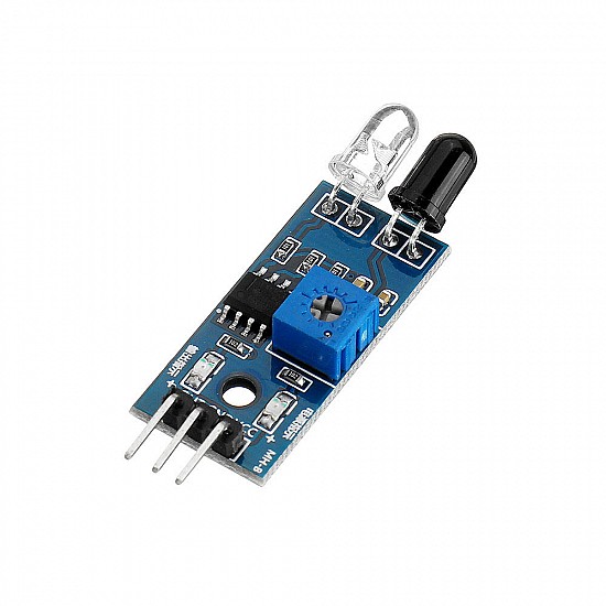
above attached image is the IR sensor used in the project (for reference)
Step 2: Signal Conditioning (The LM555 Timer) - Raw sensor signals can sometimes be "noisy" or trigger multiple false counts for a single object (contact bounce). To solve this, I routed the IR sensor's output into an LM555 Timer IC configured in monostable mode. This acts as a signal conditioner, ensuring that every time the beam is broken, the circuit produces one clean, distinct clock pulse.
.png)
above attached image is the 555 timer IC used in the project (for reference)
Step 3: The Brains of the Operation (Binary Logic Counters) - The clean pulse from the 555 Timer is fed into the clock input of the first CD4026 IC. The CD4026 is a brilliant chip that combines a CMOS decade counter with a 7-segment display decoder.
- Every pulse increments the internal binary count.
- When the first IC reaches '9' and rolls over to '0', it sends a "carry over" pulse via pin 5 to the clock input of the second CD4026 IC, effectively counting the "tens" digit.
.png)
above attached image is the CD4026 IC used in the project (for reference)
Step 4: The Interface & Reset Finally, the outputs of the CD4026 chips are wired directly to a Two-Digit 7-Segment Display to visualize the count in real-time. I also integrated a manual Push Button switch connected to the Reset pins (Pin 15) of both ICs. Pressing this instantly grounds the logic, returning the display to 00.
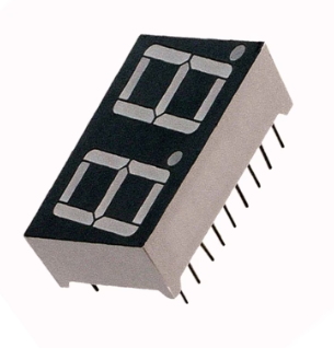
above attached image is the 2 digit 7segment display used in the project (for reference)
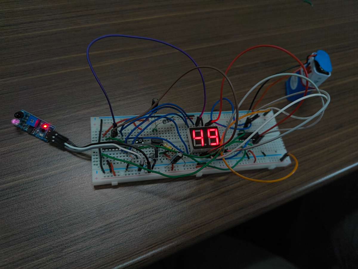
The Project after assembling as per the Circuit diagram
3. Schematic / Circuit Diagram
Below is the complete schematic / circuit diagram demonstrating how the components are wired.
.png)
4. Code Snippets
No Code Required! One of the primary achievements of this project is that it requires absolutely zero programming. It is a 100% hardware-driven system operating purely on discrete binary logic gates and clock pulses.
5. Video Submission
In the video below, I demonstrate the system successfully tracking objects (used my finger for demo purpose) detected through the IR sensor in real-time, followed by a manual system reset.