Objective
- Detect human hand gestures in real-time
- Interpret gestures using computer vision
- Control a robotic hand accordingly
- Enable natural human-robot interaction
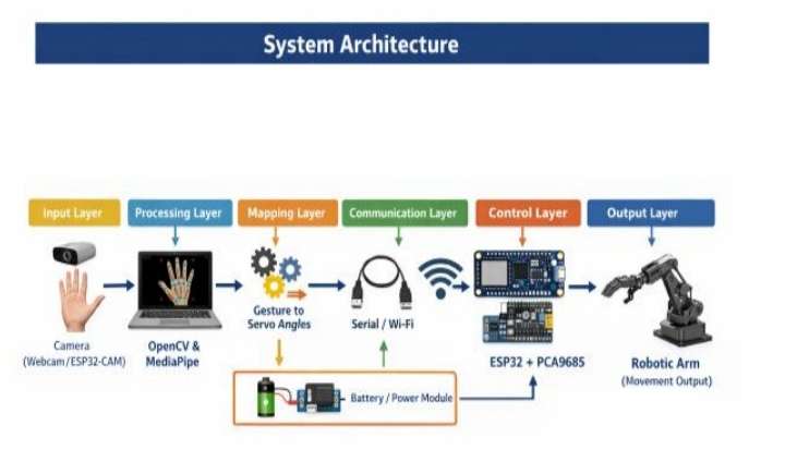
System Architecture
1. Input Layer
Camera is used to capture real-time hand gestures
(webcam or ESP32-CAM). The video stream serves as
the primary input to the system.
2. Processing Layer
A Python-based processing unit using OpenCV and
MediaPipe is used to detect hand landmarks and
extracts 21 key points of the hand in real time.
3. Mapping Layer
The detected landmark coordinates are processed and
mapped into corresponding servo motor angles. This
involves normalization and scaling of hand movement
data into predefined robotic arm motion ranges.
4. Communication Layer
The mapped angle values are transmitted from the
processing system to the ESP32 microcontroller using
Serial communication (USB UART) or wireless
communication (Wi-Fi in future enhancements).
5. Control Layer
The ESP32 processes incoming data and generates
PWM signals using the PCA9685 driver module to
control multiple servo motors, enabling precise
movement of the robotic arm.
6. Power Layer (Recommended Addition)
A regulated power supply (battery or buck converter)
provides stable voltage to the ESP32, PCA9685, and
servo motors ensuring reliable operation.
Methodology
The methodology of the gesture-controlled robotic arm
describes the step-by-step process of capturing human
hand gestures, processing the data, and converting it
into mechanical movement of the robotic arm. The
system follows a structured pipeline from input
acquisition to output actuation.
1. Step-by-Step Working Process
Step 1: Capture hand gestures in real time using a
webcam.
Step 2: Detect 21 hand landmarks (fingers joints,
elbow, shoulder and wrist) using MediaPipe Hand
Tracking integrated with Python and OpenCV.
Step 3: Process the landmarks to extract finger joint
angles and identify specific hand gestures.
Step 4: Map each finger’s movement to corresponding
servo motor angles to replicate natural hand motion.
Step 5: Servo control signals are transmitted from
Python to ESP32 / Arduino Uno through serial
communication.
Step 6: Design and build a low-cost bionic hand
prototype using 3D-printed parts, following a tendon-
driven mechanism.
Step 7: The system was tested, calibrated, and refined
for real-time, low-latency, and accurate finger
movement replication.
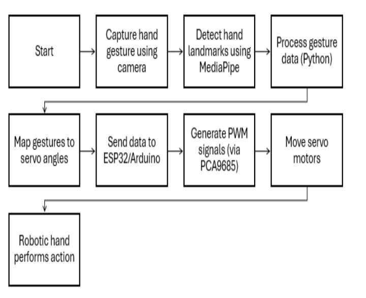
The overall system follows the following sequence:
Camera → MediaPipe → Python Processing →
ESP32/Arduino + PCA9685 → Servo Motors →
Robotic Hand
The ESP32/Arduino along with PCA9685 acts as the
control unit responsible for generating PWM signals to
drive multiple servo motors in the robotic arm.
2. Control Logic / Algorithm
The control logic defines how gesture data is converted
into mechanical motion. It ensures accurate mapping
between detected gestures and robotic arm movement.
Algorithm Steps:
1. Start system initialization.
2. Capture video frame from camera.
3. Detect hand landmarks using MediaPipe.
4. Extract coordinate values of key points.
5. Normalize and scale coordinates to servo range
(0°–180°).
6. Compare gesture values with predefined
thresholds.
7. Generate corresponding servo angle values
(planned mapping logic).
8. Send processed gesture data to ESP32 via serial
communication.
9. ESP32 processes data and generates PWM signals
using PCA9685.
10. Servo motors move the robotic arm accordingly.
11. Repeat loop for continuous real-time control.
3. Gesture Recognition Logic
The gesture recognition system identifies hand
movements based on the spatial relationships between
detected hand landmarks. Each gesture corresponds to
a specific combination of joint angles and distances.
The system continuously compares real-time landmark
data with predefined gesture patterns to determine the
intended action.
Example Gesture Mapping:
• Raising index finger → move robotic finger
upward
• Closing fist → close robotic gripper
• Tilting hand left/right → rotate base servo
This enable intuitive and real-time control of the
robotic arm.
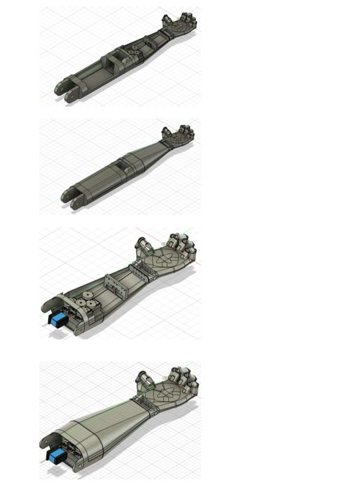
Step-by-Step Procedure For Making a Robotic Hand
Step 1: Designing the Robotic Hand
A robotic hand model was selected and prepared for manufacturing. The design included separate finger joints and mounting spaces for servo motors to enable finger movement.
Check Out The Details in CAD Design and Flow Diagram
3D model of the robotic hand:
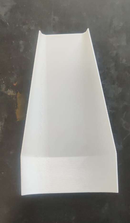
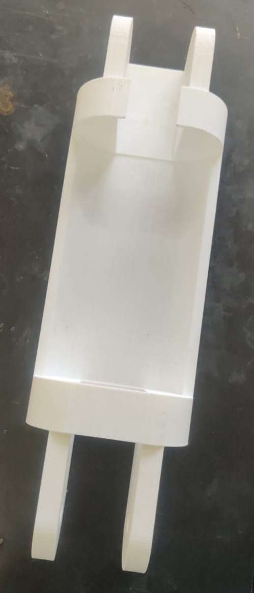
Step 2: 3D Printing the Parts
The robotic hand components were manufactured using a 3D printer. Individual parts such as fingers, palm section, and joints were printed separately. After printing, the parts were cleaned and inspected for proper fitting.
3D printing process or printed parts:
Step 3: Assembling the Hand
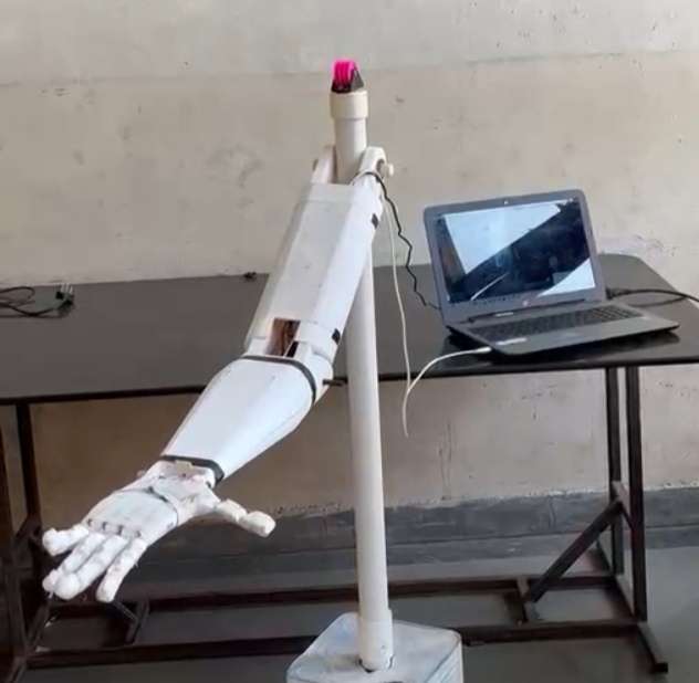
The printed components were assembled to form the complete robotic hand. Joints were connected and servo motors were installed to control finger movements.
Assembled robotic hand:

Step 4: Wiring the Servo Motors and ESP32
The servo motors were connected to the ESP32 microcontroller according to the circuit diagram. Power and signal connections were verified before testing.
Hardware Setup and Wiring of Gesture
Controlled Robotic Hand
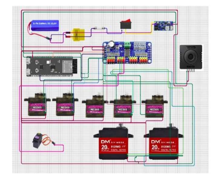
Circuit connections.
.png)
Step 5: Developing the Hand-Tracking System
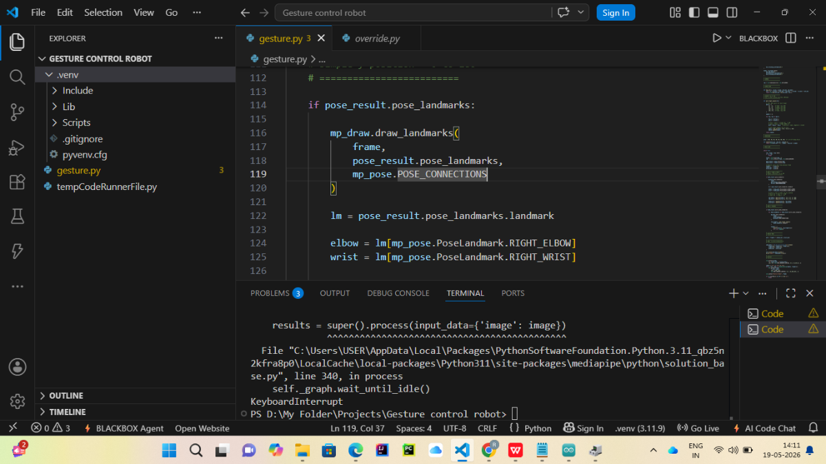
A webcam was used to capture hand movements. Python, OpenCV, and MediaPipe were used to detect hand landmarks and track finger positions in real time.
Check Out The Details in Software Code Section
Hand-tracking software running on the computer.
Step 6: Integrating Hardware and Software
The detected finger positions were sent to the ESP32, which converted them into servo motor movements. This allowed the robotic hand to mimic human hand gestures.
After Completing two above step this will be Outcome System integration setup.
Step 7: Testing and Final Demonstration
The robotic hand was tested with different hand gestures and object-grasping tasks. The system successfully replicated finger movements in real time.
Working Video
CAD Design and Flow Diagram
The robotic arm is designed using CAD software such
as SolidWorks/Fusion 360 to create a precise and
functional 3D model. The design includes multiple
joints representing the base, arm segments, and gripper
mechanism. Each joint is structured to allow rotational
movement similar to a human hand.
The model follows a tendon-driven mechanism, where
servo motors control the movement of fingers through
flexible linkages. The components are designed to be
lightweight and suitable for 3D printing, ensuring cost-
effectiveness and ease of assembly.
Key Features of CAD Model:
• Multi-degree-of-freedom (DOF) joints.
• Compact and lightweight structure.
• Provision for mounting servo motors.
• Finger-like gripping mechanism.
• Modular design for easy modification.

Flow Diagram of System
The flow diagram represents the working sequence of
the gesture-controlled robotic arm system from input
to output.
Software Code
System Overview
The project consists of two main parts:
1. Python and MediaPipe (Visual Studio Code)
- Captures live video from the webcam.
- Detects hand and body landmarks using MediaPipe.
- Calculates finger, wrist, and elbow angles.
- Sends the calculated angle values to the ESP32 through serial communication.
2. ESP32 Microcontroller (Arduino IDE)
- Receives angle values from the Python program.
- Processes the received data.
- Controls the servo motors of the robotic arm.
- Replicates the user's gestures in real time.
- Python + MediaPipe (VS Code) → Detects hand/body gestures and sends values through Serial.
- ESP32 Arduino Code (Arduino IDE) → Receives those values and moves the robotic arm servos.
Run them in this order.
Software Requirements
- Arduino IDE 2.3.8
- Visual Studio Code (VS Code)
- Python 3.11
- MediaPipe Library
- OpenCV Library
- PySerial Library
NumPy Library
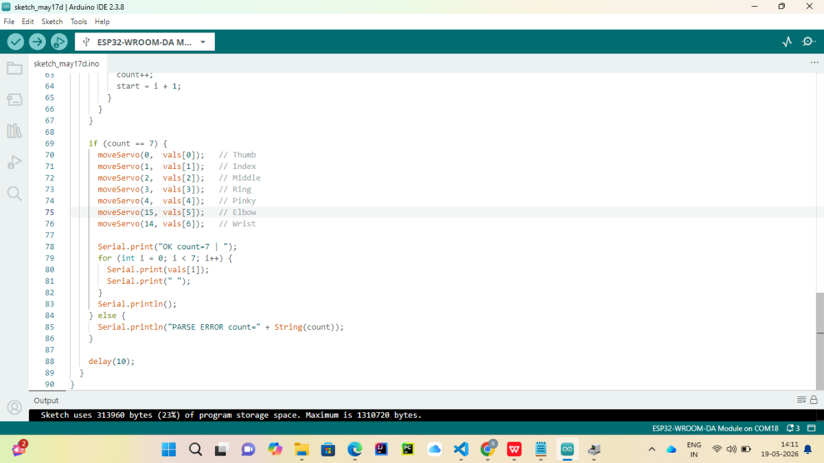
Part 1: Upload ESP32 Code (Arduino IDE)
Step 1: Connect ESP32
- Connect ESP32 to PC using USB cable.
- Open Arduino IDE.
Step 2: Select Board
Go to:
Tools → Board → ESP32 Arduino → ESP32-WROOM-DA Module
(Your screenshot already shows ESP32-WROOM-DA Module selected.)
Step 3: Select COM Port
Go to:
Tools → Port
Select:
COM18
(or whichever COM port your ESP32 appears on)
Step 4: Verify Code
Click:
✓ Verify
If no errors appear, continue.
Step 5: Upload
Click:
→ Upload
Wait until:
Hard resetting via RTS pin...
Done uploading.
appears.
Step 6: Test Serial Monitor
Open:
Tools → Serial Monitor
Set:
Baud Rate = 115200
You should see messages like:
OK count=7
or
Waiting for data...
depending on your code.
Part 2: Setup Python Environment (VS Code)
Step 1: Open Terminal
In VS Code:
Terminal → New Terminal
Activate virtual environment:
.\venv\Scripts\activate
You should see:
(venv)
before the path.
Step 2: Install Required Libraries
Run:
pip install mediapipe
pip install opencv-python
pip install pyserial
pip install numpy
Verify:
pip list
You should see:
mediapipe
opencv-python
pyserial
numpy
Step 3: Check Webcam
Run:
python
Then:
import cv2
cap=cv2.VideoCapture(0)
print(cap.isOpened())
Should return:
True
Step 4: Check Serial Port
Find ESP32 COM port.
In Device Manager:
Ports (COM & LPT)
Example:
USB Serial Device (COM18)
Remember the COM number.
Part 3: Configure Python Serial Communication
In your Python file find:
serial.Serial(
    "COM18",
    115200
)
or
ser = serial.Serial('COM18',115200)
Replace with your actual COM port.
Example:
ser = serial.Serial('COM18',115200)
Part 4: Run Python Gesture Detection
Inside VS Code terminal:
python gesture.py
Camera window should open.
You should see:
- Hand landmarks
- Pose landmarks
Angle values
Part 5: Test Data Transmission
Add temporarily:
print(data)
before:
ser.write(data.encode())
You should see something like:
90,45,30,20,10,80,70
continuously.
Part 6: Verify ESP32 Receives Data
Open Arduino Serial Monitor.
Expected:
OK count=7 90 45 30 20 10 80 70
If you see:
PARSE ERROR
then Python is not sending the format expected by ESP32.
Ctrl + C
and manually stopped the Python program.
Final Running Sequence
Every time you start the project:
1️⃣ Upload ESP32 Code
Arduino IDE → Upload
2️⃣ Open Serial Monitor Once
Check ESP32 is alive.
3️⃣ Close Serial Monitor
Important: only one program can use COM18 at a time.
4️⃣ Run Python
python gesture.py
5️⃣ Show Gesture
Camera detects:
- Thumb
- Index
- Middle
- Ring
- Pinky
- Elbow
- Wrist
6️⃣ ESP32 Receives Values
ESP32 moves servos accordingly.
Processing Data in ESP32
Step 1: Receive Serial Data
The ESP32 continuously monitors the serial port for incoming angle values.
Step 2: Parse Received Values
The received data is separated into seven angle values corresponding to:
- Thumb
- Index Finger
- Middle Finger
- Ring Finger
- Pinky Finger
- Elbow
- Wrist
Step 3: Control Servo Motors
The ESP32 assigns each angle value to its corresponding servo motor.
Step 4: Move the Robotic Arm
The servo motors rotate according to the received angle values, causing the robotic arm to mimic the user's hand and arm movements.
Testing Procedure
Test 1: Open Hand Gesture
- Start the Python program.
- Place an open hand in front of the webcam.
- Observe that all finger servos move to the open position.
Test 2: Closed Hand Gesture
- Form a fist in front of the webcam.
- Observe that the finger servos move to the closed position.
Test 3: Wrist Movement
- Rotate the wrist.
- Verify that the wrist servo follows the movement.
Test 4: Elbow Movement
- Bend and straighten the arm.
Verify that the elbow servo follows the detected motion.
Expected Results
- The webcam successfully captures live video.
- MediaPipe accurately detects hand and body landmarks.
- The Python program calculates joint angles in real time.
- Serial communication between the computer and ESP32 functions correctly.
- The ESP32 receives and processes the transmitted angle values.
- The servo motors respond according to the detected gestures.
- The robotic arm accurately reproduces the user's hand and arm movements with minimal delay.
Overall Outcome
• The developed system aims to be a low-cost,
intelligent robotic arm that uses AI, computer
vision, and embedded control for real-time
gesture-based operation.
• Touchless Control: Enables safe and hygienic
hands-free operation.
• Low-Cost Design: Built using ESP32-CAM,
servos, and 3D-printed parts.
• Educational Use: Useful for learning AI and
OpenCV concepts.
• Industrial Use: Supports automation, assembly,
and remote handling.
• Scalable System: Can be upgraded with object
detection or voice control.
Working Video:
Final Look: