
The Challenge: Flaws in Existing Emergency Lights
Current market solutions for power outages fall into two categories, both of which have significant limitations:
- Standard Emergency Lamps: These are entirely manual. They do not have automatic detection, meaning users must fumble in the dark to find the switch. If left on by mistake, they drain the battery completely.
- Commercial Rechargeable Bulbs (Inverter Bulbs): These bulbs screw into standard sockets but have a major design flaw: Charging inefficiency. To charge the internal battery, the wall switch often needs to be kept in the 'ON' position. This frequently leads to situations where the light is ON when not needed, simply to ensure it charges, resulting in a significant wastage of electricity.
The Solution:
This project bridges this gap by creating a system that is fully automated and energy-efficient.
Intelligent Automation: Unlike manual lamps, this system uses an LDR to constantly monitor ambient light. It only activates when the environment requires light.
Advanced Touch Control: The TTP223 sensor is not just a switch; it provides two advanced features:
- Dimming: Long-pressing the sensor adjusts the brightness via PWM, allowing the user to save battery or set the mood.
- Soft-Off: To prevent accidental blackouts (common with sensitive touch sensors), I programmed a "Grace Period." When you tap to turn off, the lamp blinks and waits 5 seconds before actually cutting power. If you touch the sensor again during this countdown, the shutdown is cancelled. This ensures you never have to fumble in the dark due to an accidental touch or false trigger.
Working
It reads the LDR sensor 50 times rapidly with a 1ms delay between each read and calculates the average of these 50 readings to get a stable, reliable value representing the current ambient light.
In the code, a higher value (> 800) means Dark, and a lower value means Bright. The lamp turn on or off according to these values.
The clever part to stops the lamp from rapidly turning on and off (flickering).
When the lamp turns on in a dark room, the room suddenly becomes bright. If the Arduino checked the light level normally, it would think "it's bright now!" and turn the lamp off immediately. This would cause the light to flicker on and off endlessly.
Therefore after Immediately turning the LED on, the code waits 500ms to let the light stabilize.
Then takes a new reading of the brightness (which includes the lamp's own light) and saves it in a variable called current_reference.
This value effectively becomes the new baseline. The Arduino is now saying, "Okay, this brightness level is the new 'Dark'. I will ignore this much light."
Connection Guide
1. Power Supply (TP4056 & Battery)
This module handles charging and powers the Arduino. Atmega328 can run from 1.8V to 5V, since a Li-ion battery voltage is between 3.5V to 4.2V. So you can directly connect the battery to Arduino.
- Battery + ------> TP4056 B+
- Battery - ------> TP4056 B-
- TP4056 OUT+ ------> Arduino Nano 5V Pin (and to LED Anode)
- TP4056 OUT- ------> Arduino Nano GND
2. Inputs (Sensors)
LDR (Light Dependent Resistor)
- LDR Leg 1 ------> Arduino 5V
- LDR Leg 2 ------> Arduino A1
- Resistor Leg 1 ------>Arduino A1 (Same as LDR Leg 2)
- Resistor Leg 2 ------>Arduino GND
TTP223 Touch Sensor
- VCC------>Arduino 5V
- GND ------> Arduino GND
- I/O ------>Arduino D6
3. Output (LED & MOSFET)
IRFZ44N MOSFET
The MOSFET acts as a switch controlled by the Arduino.
- Gate (Pin 1) ------>Arduino D11
- Drain (Pin 2) ------>LED Negative (Cathode)
- Source (Pin 3) ------>Arduino GND
LED
- LED Positive (Anode) ------>TP4056 OUT+ (or Arduino 5V)
- LED Negative (Cathode) ------>MOSFET Drain
The fritz diagram
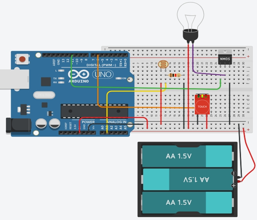
The tp4056 is missing from this diagram but i have uploaded complete schematic. you can find it HERE.
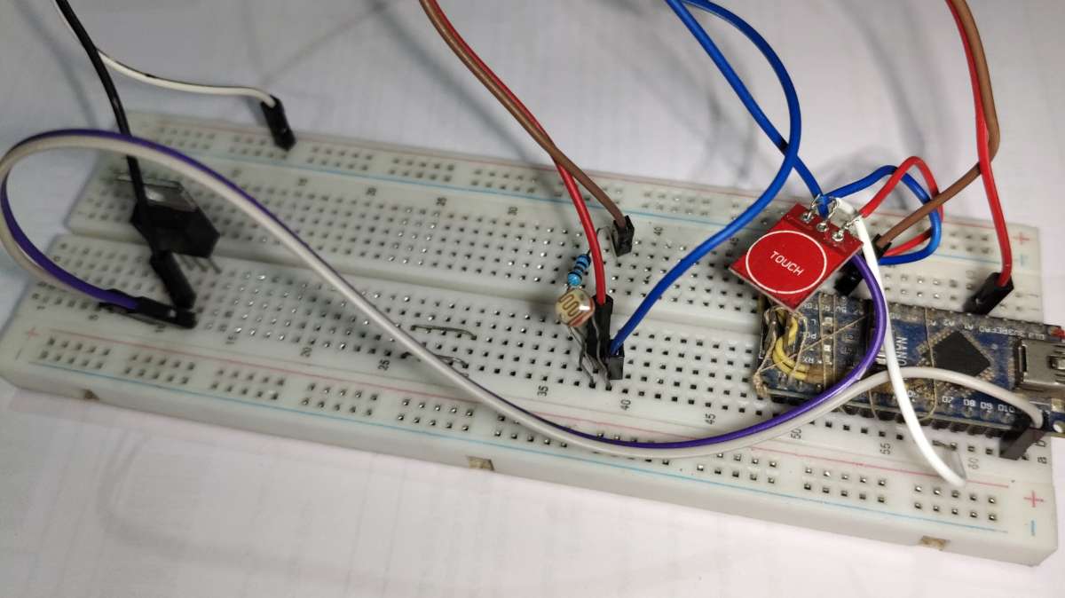
The Prototype
You can see a red touch sensor on the right side in the video.
Testing the dimming feature
Testing overall features