
Components List | |
| NAME | QUANTITY |
| ESP32-C6-N8 | 1 |
| ESP8266 | 1* |
| Step Down Transformer | 1 |
| Relay Module | 5* |
| Current Transformer | 1* |
| Triac | 1* |
| Optoisolator MOC302x | 1* |
| Shift Register 74HC165 | 1* |
| 3.3V power supply module | 1* |
| Some Resistors | |
| *for each rooms/switchboards (You can use more or less as their requirement) | |
| BOM using Digikey mylist: https://www.digikey.in/en/mylists/list/G6A42UPKSZ?cur=INR | |
In this project, I have built an advanced, distributed Home Automation System based on the energy-efficient ESP32-C6 as the central hub and ESP8266 nodes for individual rooms. Unlike common smart home projects that are often limited to controlling just a single room's appliances within direct range, this system can effortlessly manage the entire house by creating its own intelligent mesh network using ESP-NOW.
It uses cryptographic hashing to prevent replay attacks, a self-healing topology that reroutes data if a node fails, and active electrical safety cut-offs.
Key Features:
- Smart Scheduling: Users can set automated timers for any appliance (e.g., "Turn ON Porch Light at 6:00 PM", "Turn OFF Geyser at 8:00 AM").
- Dimming & Speed Control: Instead of just On/Off buttons, the app provides Sliders to smoothly dim lights or adjust ceiling fan speeds.
- Dual-Mode Control: The Appliances can be controlled using the Smartphone OR existing physical wall switches.
- Active Safety Protection: The User can set limit for Voltage and Current for each Rooms. The system automatically cuts power in case of High Voltage surges, Over-Current, or Short Circuits.
- Power Analytics: It can displays live power uses and graphs of power consumption and saves historical data, allowing users to view Daily, Weekly, and Monthly energy usage.
- Intelligent Self-Healing Network: Standard setups fail if the WiFi signal is weak in one room. My system actively detects a lost connection and uses other ESP8266 nodes as "Bridges" to relay the message, effectively creating a dynamic mesh network.
- Smart Overload Management: Instead of a dark house when the toaster and heater run together, this system simply turns off the heater to save the fuse, while keeping the lights on.
No Internet Required: The system is entirely web-based and hosted locally on the ESP32. You don't need to download suspicious third-party apps, sign up for cloud accounts, or even have an active internet connection. It works perfectly on your local WiFi network, ensuring maximum privacy.
Advanced Control System
Behind the scenes, the ESP32C code handles complex actuation and memory tasks to ensure the system feels professional and responsive.
1. Hybrid Actuation (Relays & TRIACs)
- Relays: Used for heavy loads like ACs, Geysers, and Water Pumps to ensure isolation.
- TRIACs : Used for lights and fans. By detecting the AC Zero-Crossing point, the ESP8266 chops the sine wave to control intensity, allowing for smooth dimming and fan speed regulation
2. Power-Loss Recovery
This system saves the exact state (On/Off status and Dim level) of every device to the ESP8266's non-volatile memory. When power returns, the devices restore themselves to their previous state. If the lights were off, they stay off.
3. Fail-Safe Physical Control (Works Offline)
The physical switch inputs are locally managed by the node. This means even if the WiFi is down, the physical switches work instantly with zero lag. The new state is then synced to the app once connectivity returns.
4. Shock-Proof Low-Voltage Switching
Traditional wall switches carry dangerous live 220V AC and sometimes shock when operated with wet hands. In this system, the physical switches connect to the ESP8266 using a logic-level 3.3V DC signal.
- This completely eliminates the risk of electric shock.
- It is safe to operate the switches even with wet hands.
Security & Network Intelligence
This section covers the protection mechanisms that make the system resilient against hacks and electrical faults.
Self-Healing Mesh Topology
The system does not rely on a star topology (where everyone talks to the center). If the Hub cannot reach the "Kitchen Node," it automatically routes the message through the "Living Room Node". This self-healing capability eliminates dead zones in large houses.
Login Portal:
Accessing the control dashboard requires a secure login. Even if a guest connects to your home WiFi, they cannot toggle switches without your credentials.
Cryptographic Hashing:
Internal communication between the ESP32 Hub and ESP8266 Nodes is signed with a cryptographic hash. This prevents "packet injection attacks" where a malicious person might try to creates a packet and send your signals
The UI Design
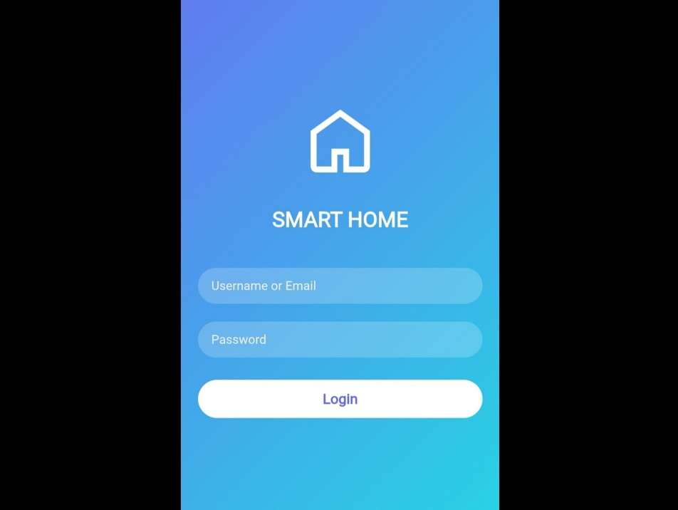
Login Page
you will be welcomed with the login page. The default login and password is admin and home.
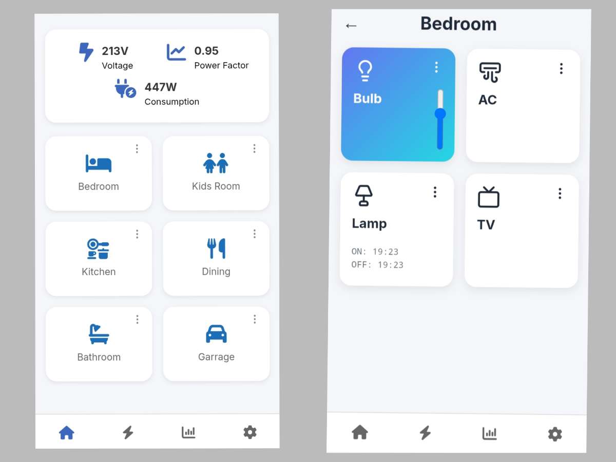
Dashboard and Control panel.
In the picture on left side, the top status bar shows the current voltage and power consumption, while below shows button with name.
the picture on right side, is of Control panel. It can be use to control appliances. You can turn ON, OFF or use slider to dim. Additionally you can also set schedule ON and OFF by clicking on three dots and selecting schedule option.
User can easily change the icon and name of buttons by clicking on three dots and selecting the modify option.
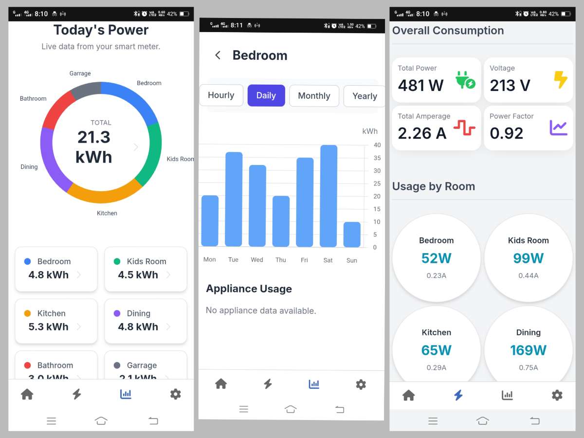
Energy Analytics
power consumption history on first and second picture and live power consumption data on third picture
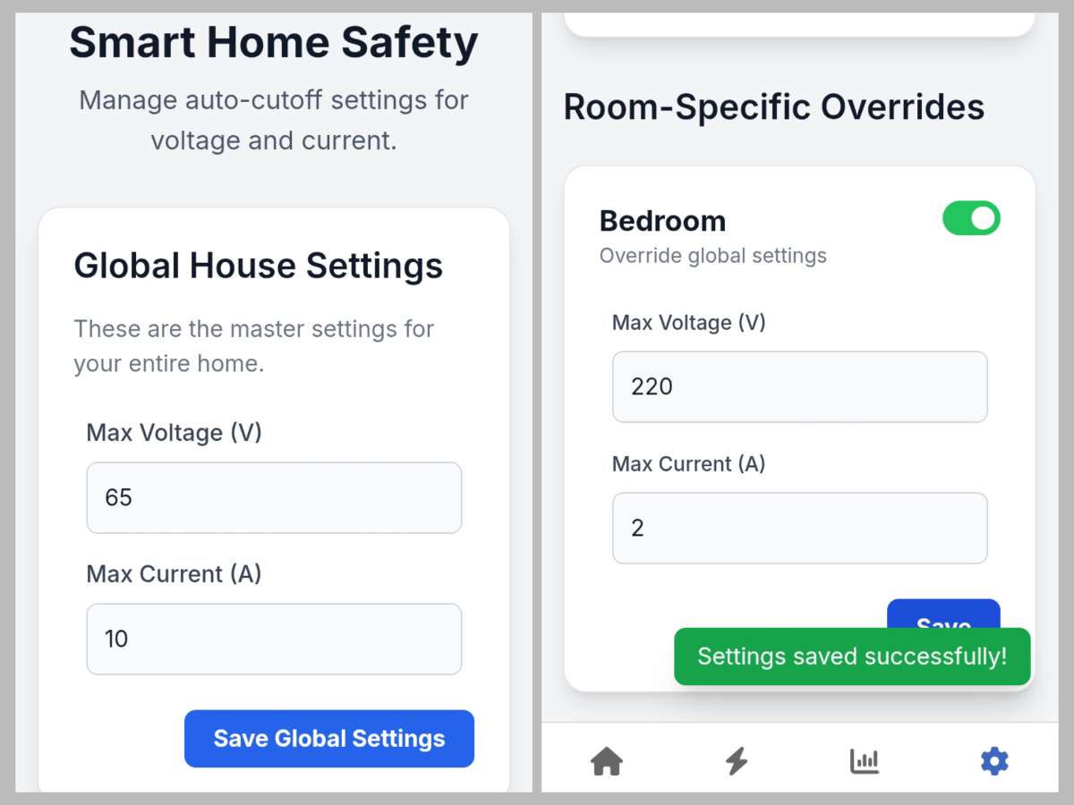
Safety Settings
On this page User can set limit for Voltage and Current for each Rooms or Global setting which apply if room settings turned off
Prototype & Testing
During testing, I set a current limit and turned on multiple devices. The system successfully detected the overload and automatically turned off the high power consuming device while keeping the lights running. This intelligent management proves the system is viable for real-world energy management.
Testing the Wireless Range
One of the primary concerns with wireless home automation is signal penetration through walls. To verify the robustness of the ESP-NOW protocol between the ESP32-C6 (Hub) and ESP8266 (Node), I conducted a practical range test.
- Test Environment: A multi-room residential building with standard brick and concrete construction and ESPs with 20cm extra wire connected to pcb antenna.
- Result: The system established reliable, low-latency communication at a distance of 20 meters (approx. 50 ft) even with 4 concrete walls obstructing the direct line of sight.
This impressive range is further enhanced by the Intelligent Mesh Topology. Since the network reconstructs itself, if a specific node happens to be out of range, it will automatically route its data through an intermediate node, extending the coverage without requiring any WiFi repeaters.
Calibrating the AC Power Measurement:-
Since this project uses a voltage step-down transformer (via the ZMPT101B module) and a CT Coil for current sensing alongside the EmonLib library, precise calibration is required to get accurate Power (Wattage) readings.
- Voltage Calibration: In the code, the function
emon.voltage(Pin, Calibration_Value, Phase_Shift)sets the scaling.- Measure the real AC mains voltage using a high-quality Multimeter (e.g., 230V).
- Check the value shown in the Serial Monitor (e.g., 215V).
- Adjustment: If the sensor reads low, increase the
Calibration_Value. If it reads high, decrease it. Repeat until they match. - formula: New Calibration value = ( Old Calibration * real voltage)/ESP voltage Reading
- Current Calibration: Similarly, for
emon.current(Pin, Calibration_Value), connect a known resistive load (like a 100W incandescent bulb).Adjust the Current Calibration value in the code until the Serial Monitor shows the correct Amperage (
Watts / Voltage)
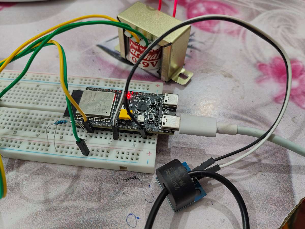
Measuring AC voltage from transformer and current from CT
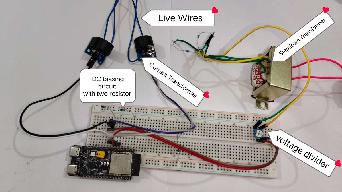
The circuit is very simple, A step-down transformer output is connected to voltage divider (potentiometer) to reduce the voltage, which then feeds to DC biasing network—using two resistors to lift the AC wave to 1.65V—before entering the ESP32's analog pin.
Simultaneously, a Current Transformers (CT) clamps around the live wire to induce a signal representing the load current. This CT output is passed through a similar DC biasing circuit to shift the AC signal above 0V making it compatible for ESP32's analog analog measurement. You need to connect one CT for each room.
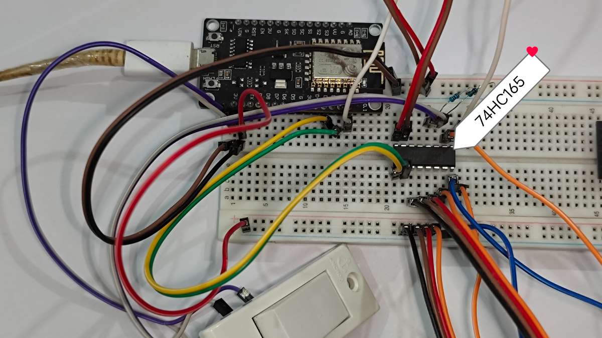
Using 74hc165 shift register to read 8 physical switch with only using 3 gpio pin of esp8266
Demonstration: Safe Low-Voltage Simulation
In this setup, i have used 18v AC to demonstrate the working.
This setup allows me to touch the components and demonstrate the wiring without risk of electric shock. The software logic remains exactly the same as the high-voltage version
I have tested the power monitoring functionality and it does work, the graphs doesn't change instantly and you will not see any changes in a 5min video.
This system is capable of controlling more switches and nodes ( max 8*8, total 64 electrical appliances) and can work with 220v AC.
Testing the device control with smartphone and physical switch
Webpage config video
The webpage required first time configuration, by default it uses name like room 1,2,3... and switch 1,2,3.....
user can change the name and icon whenever they wants.
Accessing The Webpage
For IOS: Connect to same wifi network ESP connected and type smarthome.local on web browser to access the webpage.
For Android:
method 1:
- Connect to same wifi network ESP connected
- Install Bonjour Browser from play store
- Open the app, in few second you will see the ESP32 with ip address. click on it to access the webpage.
- Create shortcut for the website (How to add shortcut ?)
Method 2:
- Connect the ESP32 with PC and open serial monitor
- The ESP32 print IP Address on serial monitor, copy it.
- Paste the IP Address on web browser to access the webpage.
- Create shortcut for the website (How to add shortcut ?)
These are one time setup, once you created the shortcut from web browser, you can easily access the webpage.
Live Demo:
I have hosted a Web-Based Simulator to demonstrate the User Interface and logic without requiring physical access to the hardware prototype.
- Simulation Mode: The dashboard generates realistic random fluctuations for voltage and wattage to demonstrate how the gauges and charts respond in real-time.
- Interactive UI: You can toggle switches, adjust dimmers, and modify safety limits just like the real device.
Link to Live Demo: https://abtamit.github.io/esp32-smart-home-demo/login
Uploading The Code
Before uploading the code to boards, you need to change some parts of code to improve the security and working of the project
In the ESP32C6 code you need to change these
#define pageName "smarthome"                  // name of webpage, default is "smarthome.local"
const uint8_t NumberOfNodes = 6;             // enter number of node (esp8266) you want to connect

const char *http_username = "admin";         // username for login on webpage
const char *http_password = "home";          // password for login on webpage
const char *ssid = "WifiName";               //Name of your WiFi
const char *password = "12367890";           // Password of your WiFi


//  hmac_key[] should be same on all devices
char hmac_key[] = "HashkeyShouldBeExcatly32letter12";  // must change the key for better security (Should must Be Excatly 32 letter including spaces)
for ESP8266 change these values in code
#define numberOfSwitch 6                               // number of switches you want to use
const uint8_t deviceId = 101;                          // must be different for every esp8266 (must be like 101,102.......106)
char hmac_key[] = "HashkeyShouldBeExcatly32letter12";  // must change the key for better security (Should must Be Excatly 32 letter including spaces)
//  hmac_key[] should be same on all devices
The code for ESP32 in a zip file and you need to unzip and open the folder in Arduino IDE to upload to the board
Note: the code are only compatible for esp board core 3.3.x and above. if you are using board core 2.x or lower, you need to update your esp board core to 3.3.x.
Code link :- https://github.com/abtAmit/Smart-Home-Energy-Monitor-and-Safety-System