
Description
Over the years, companies and hotels are known to consume electrical power due to the use of significant loads. Inherently, the energy consumption is 24/7 and because of this, they need a constant power supply. At an instant when there is a power outage from the mains (usually in some countries), there is a mandate for an automated-alternative energy source to put loads to work. This induces the motives for automation or an automated changeover system.
There is every possibility that when changing over occurs for the alternative energy source, all the loads would be powered ON at once, with exponential current drawing, which could lead to a surge, weakening the coils.
If the alternative energy source is a generator, it does not matter what Kva it is, the instant loading could cause a surge(s) in the windings of the alternators.
Likewise, if it is an inverter, it will experience sudden current drawn in the driver + amplification sections and the step-up transformer's windings, wearing the components and coils.
Solution
To offer in-demand solutions to these, I designed a prototype of an automated step-loading system plus a changeover circuit with the knowledge of IoT.
The technique is to divide the loads into 4 sections: lighting, socket, inductive and resistive loads.
The step-loading coins its name from the sequential power ON throughout the system at an interval of time, and this happens when there is the need for an alternative energy source.
When in grid/mains mode, all the loads are powered at once. While in the alternative power mode, say generator/inverter, lighting loads are powered first, followed by the sockets, then inductive loads, and lastly resistive loads.
Making
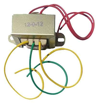
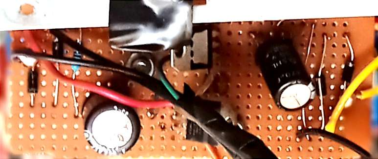
The making begins from the two centre-tapped transformers (12-0-12v, 300ma), each serving as a sensor for the two modes. One is connected to the mains source and the other to the alternative source.
They are then rectified to 12v-DC with the use of diodes, IN4148.
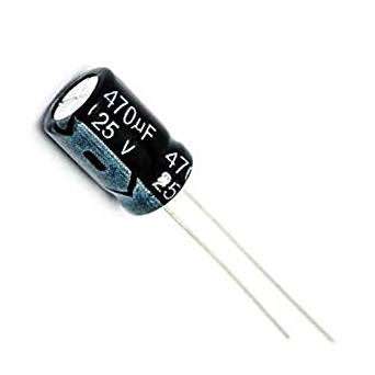
And then filtered to remove the residual of the AC to smooth the DC output with the use of 470uf, 25v capacitor.
Here, the ripples are regulated.
Read more about this: https://www.electronics-tutorials.ws/blog/unregulated-power-supply.html
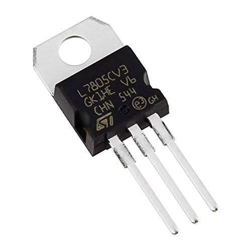
The Uno board's input voltage does not exceed 5v, therefore, to feed inputs to the microcontroller, a 12V-DC is regulated with the use of the LM7805 regulator.
The overall diagram which serves as the sensor for the two modes: mains & alternative sources is shown below:

The Arduino Uno's ATMEGA328 is the microcontroller which could be seen as a CPU Cortex of a microprocessor.
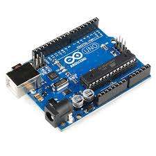
The serial communication between the Arduino, computer and the device (loads), helps to have insights into the inputs and outputs.
Serial.begin(9600);The output pins are the 8channel-5v relay, which is connected to the loads.
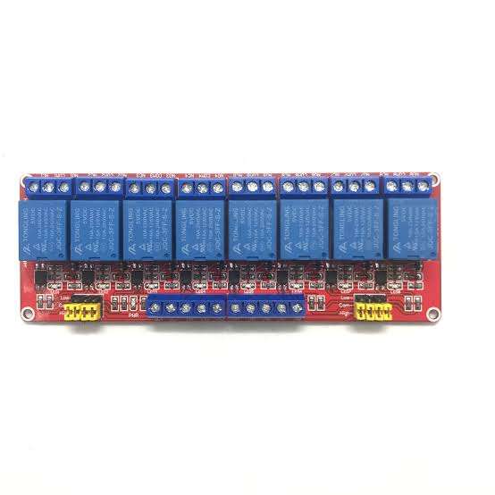
Two relays were used for each load's Live (L) and Neutral (N).
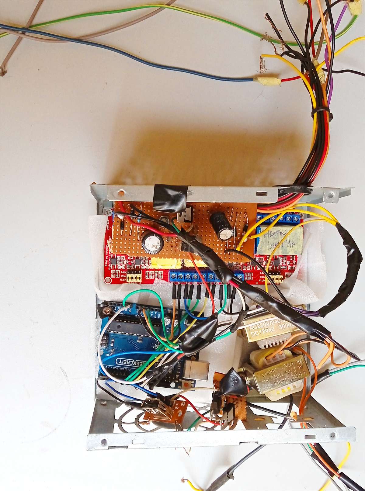
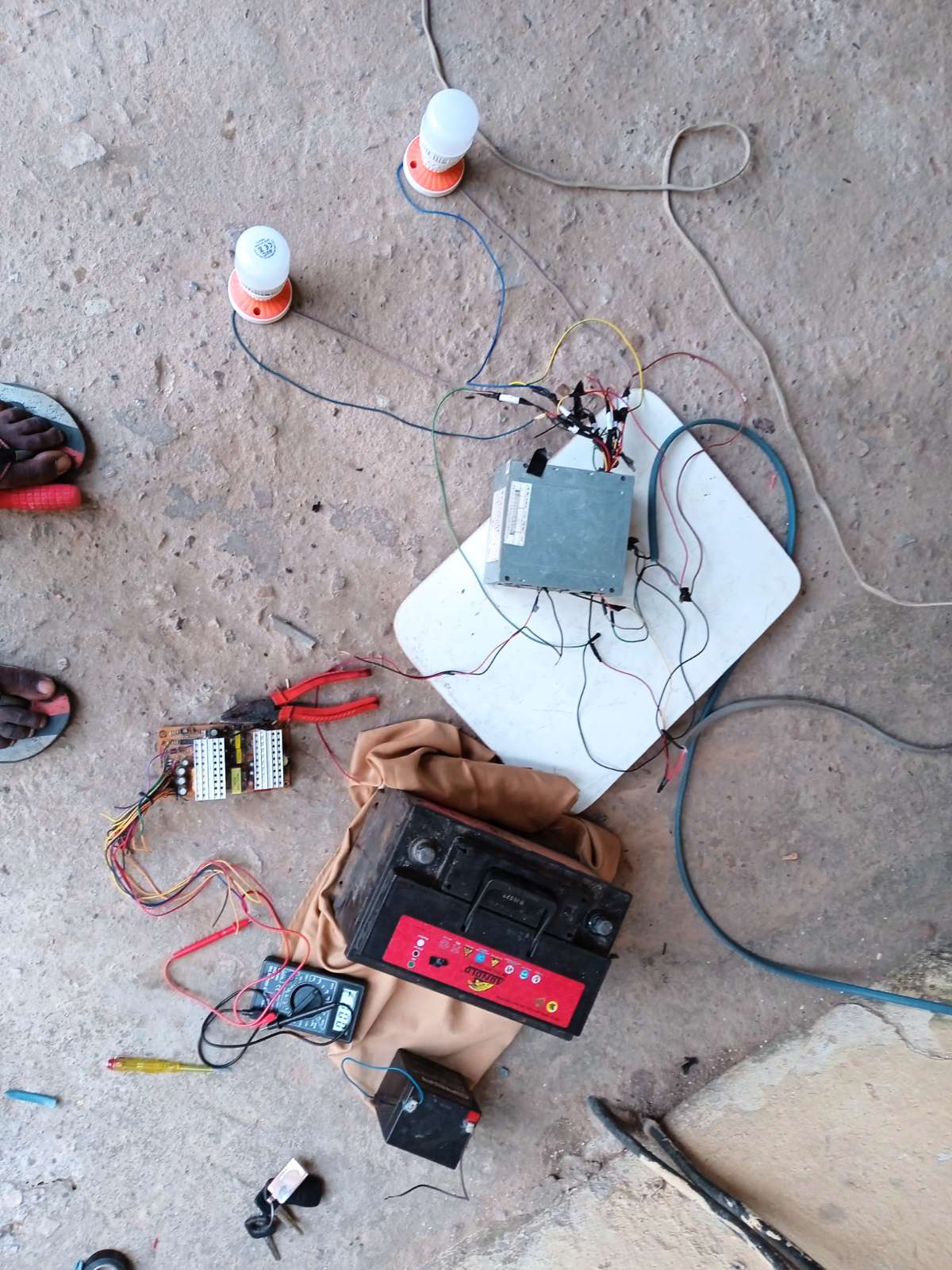
While testing for the Mains-Generator system, set up for the project is shown below:
Benefits
In terms of home and industrial usage, this can help prevent surges and for energy savings.
The sensibility that each loads' types have their controlling part, could make it easy to POWER OFF any unneeded section, especially where there are need to add more loads to the other sections (also, the surge is being protected)
This can also help in reducing loads for energy storage ( for sustainability) and help inform about what is consuming energy.
In hotels or at home, power consumption is always at the zenith, when considering weather conditions (harmattan and raining season), timely, there would be no need to use WATER HEATING SYSTEMS (electrical power consumer), this output section can be temporarily shut down for other sections and at the verge of this, there is energy-saving and energy sustenance.
Video on YouTube:
This is a prototype of the project, for high amperage design, contactors can be used.