
Idea Description:
- Hi everyone first of all thanks for viewing my project. In this project I was build an Ai Virtual Assistance with IOT based smart switch Board.
- Today home automation is everywhere and we are also use them for controlling our home appliances using mobile app , voice assistance and as well as manually.
- But in this project we are going to 4th way to control our appliances using Ai vision And I also made a homemade IOT based smart switch board in this project.
- I hope you like my concept.
Project Used Hardware:
- ESP12-e, Relays, SMD Diodes, SMD Resistors & transistors, SMD Buttons, 2pin connectors, Copper Clad, Plugs, Dummy switches, Electric Board, Wires, Computer for AI Virtual Assistance, Webcam for AI Vision, AMS1117 3.3V power ic, 3mm Leds, Hi-link 5v/5w.
Project Used Software:
- Arduino IDE, PyCharm, Python 3.7.6, Blynk Cloud server, Mit App Inverter, EasyEDA PCB Designer.
What I have done in this project?
- IOT based smart switch board.
- Ai Virtual Assistance

IOT based smart switch board:
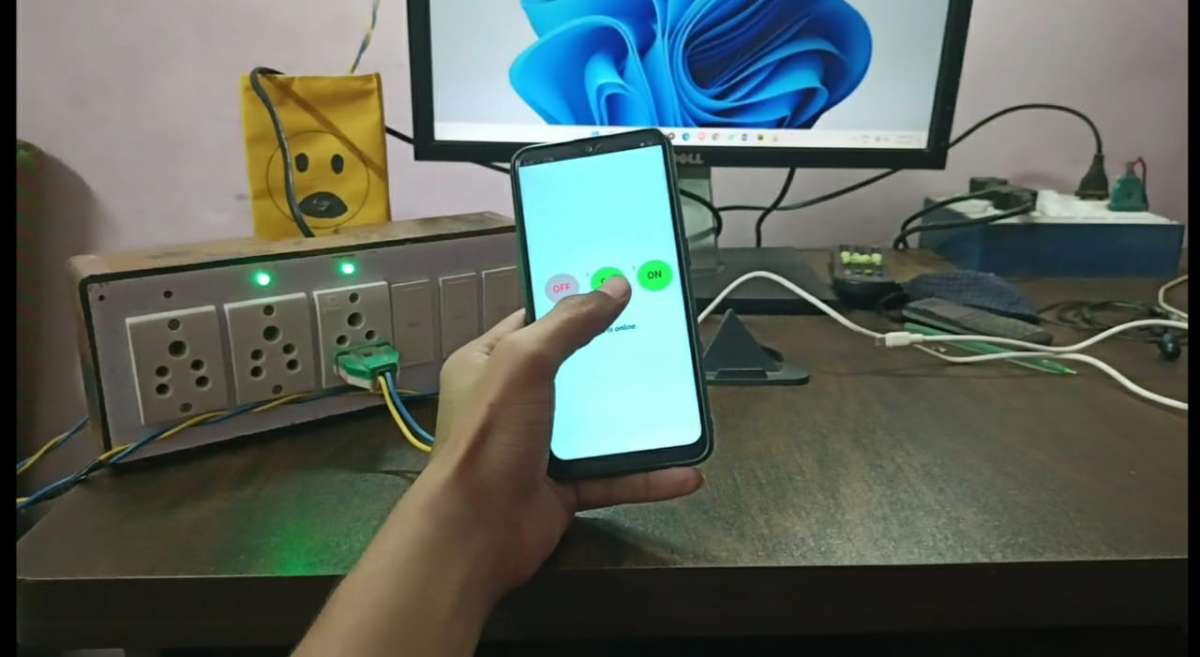
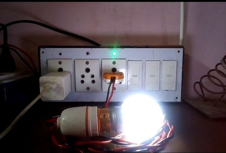
- In this project I have made an IOT based smart switch board. Which you will be able to control from anywhere in the world, that too with the help of internet. And we will control it with our hands too using a virtual assistant.
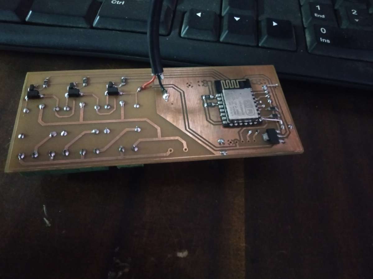
- First I designed a PCB and later I did soldering by putting components on it.
- And after that I wrote the code in Arduino IDE which I uploaded to our ESP12-e (Wi-Fi module).
- I have used blynk cloud server to connect this switch board with internet.
- Then I went to a website called Mit App Inventor, which is a website for making Android apps. Here I use a blynk API to create my App.
- After doing that, I made my own personal app for my smart switch board.
- After this, I connected our designed circuit and the components of the board according to the circuit diagram. And our smart switch board is ready.
Ai Virtual Assistance:
- In our AI Virtual Assistance I have use camera as a Ai Computer Vision and I have also add a voice for feedback and also design a dashboard for feedback in our assistance. Our AI Virtual Assistance is a software based application that you can do on any laptop or computer.
- First I go to pycharm and install some library like opencv, mediapipe and requestss.
- After this, I write the code in Python and create a hand detector model. Which we will use in this project to detect the hand.
- After I detect hand then I set my hand position for gesture.
- And here our last less is left which is to connect our smart switch board with internet.
- Here my idea is very simple. I used a requestss (it’s basically python library to use of http request) for run Blynk API in background in our python script.
- After setting up the requests I created a dashboard that would give us feedback on our laptop screen like our hand is detected or not & our room light is on or off.
- After all of this, We are also convert this python file into exe file. And by installing this file in any laptop, we are able to use this Assistant.
- And here I completed my Ai Virtual Assistant.
.jpg)
Schematics and Circuit Diagram:

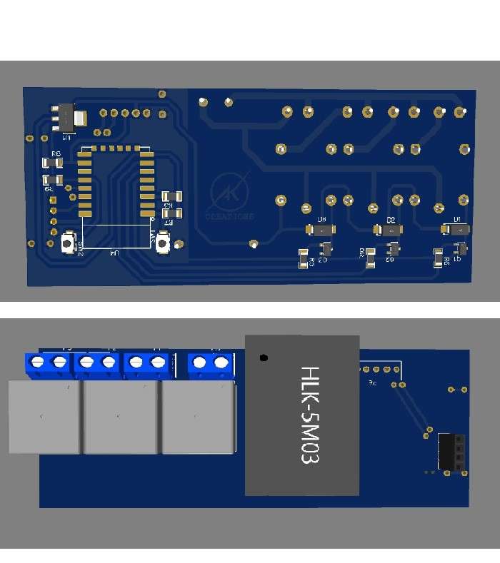
- So our circuit diagram is very simple. I have used Esp12-e in it and to program it I have also kept the pin of RX/TX. Then I have connected 3 pins of Esp12-e with relay and the other 3 pins are kept for input of touch sensor. And I have used a Hi-Link power supply to power the entire circuit. Here I am also used 2 pin connectors for connecting board wiring. And our circuit diagram is ready. And one thing, I have used some resistors inside it. Which does it to pull up and pull down some pins of esp12e.
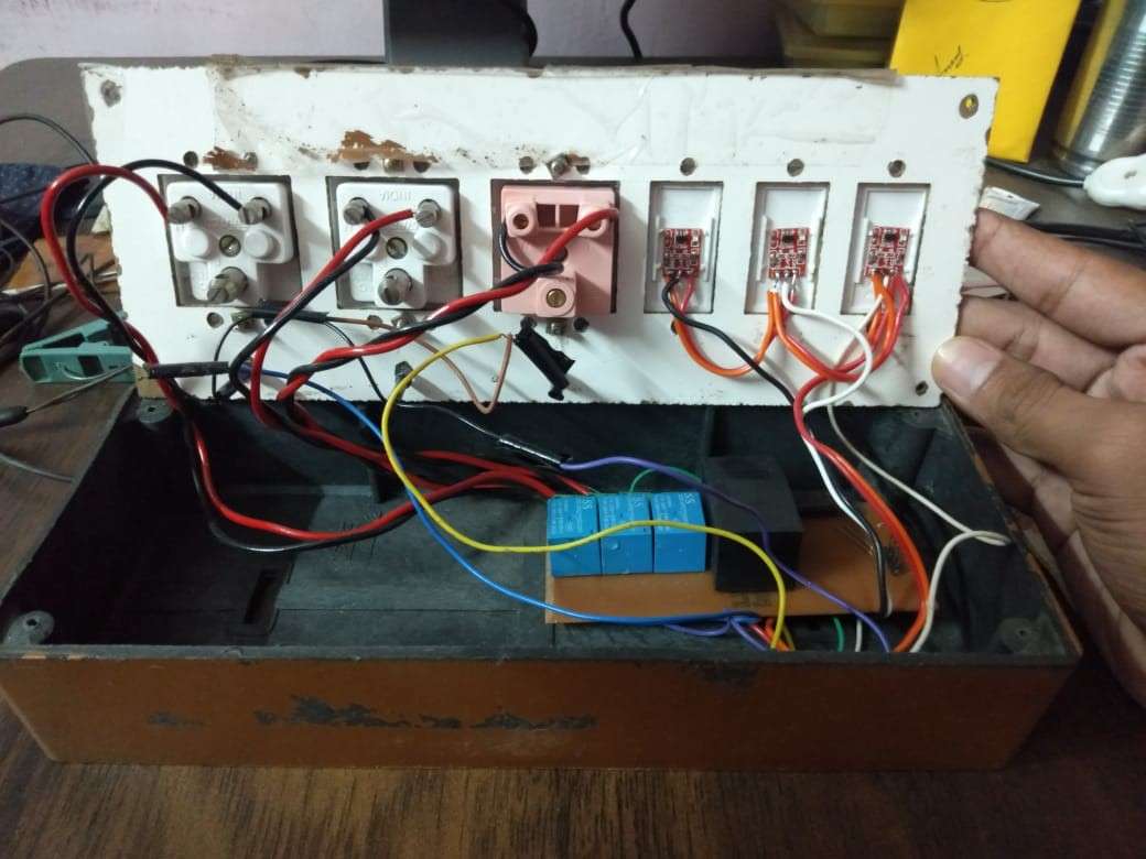
Connection Diagram of Board:
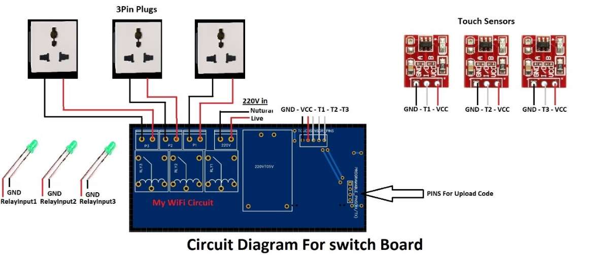
- The circuit diagram of the board is the connection of the main hardware of our project. Inside which we put the circuit containing our Wi-Fi module.
- First of all, I connected 3 plugs to our Wi-Fi circuit using wire. And after that I also connected the touch sensor. And I also put 3 LED lights inside this diagram. Which will tell the status of our plug whether the plug is on or off. And I have taken the input pin of this LED from the input pin of the relay. And finally, I have a 220V power supply connected to our Wi-Fi circuit. And our smart board is ready.