
Let's talk about Mecanum wheels. They are awesome and full of magic and I think everyone should try them once in their lifetime.
You will find many DIY projects on the internet but none of them seems to program these correctly. Mecanum wheels are weird so you can't just attach them to motors like regular wheels. We have to consider the mechanics of the Mecanum wheel while programming them.
In this article, I will show you how to make your own Mecanum wheel robot and program it correctly.
You can contact me on Instagram or Discord if you need any help
Mechanics of the Mecanum wheel
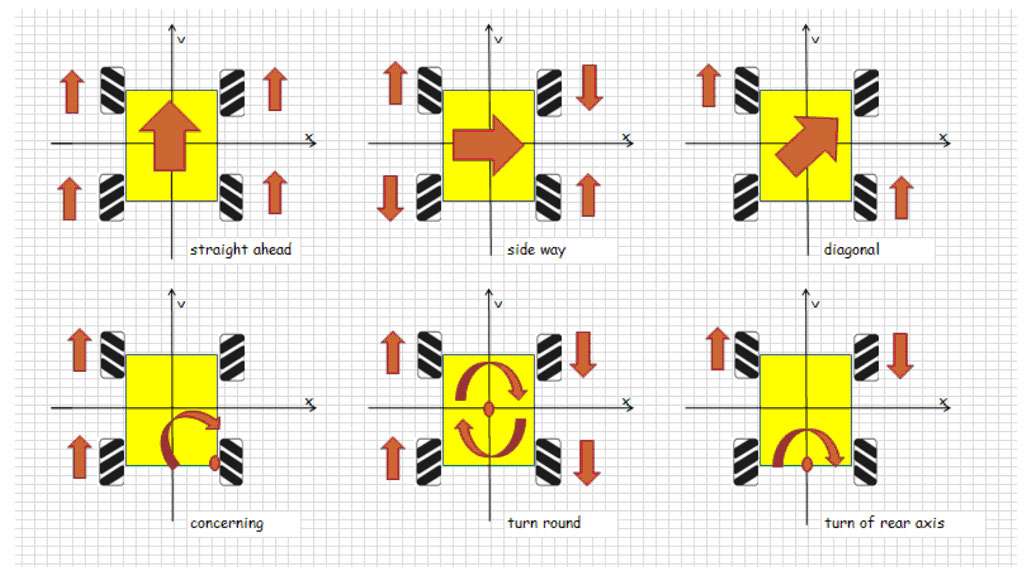
Instead of steering Mecanum wheels mechanically, we vary the motor speed and spinning direction to control the movement of the robot. Varying the motor speeds and spinning direction will produce movements in different directions. Please refer to the diagram above red arrows tell us the motor and robot spinning direction. I have explained this concept in the video.
.png)
Imagine a robot moving forward then all the forces acting on the wheels will look like this. Now if we try to find out net forces acting on the robot all the forces acting in the X direction and marked in red will cancel each other because they are in the equal and opposite directions to each other. The force in the Y direction will remain because they are parallel and are in the same direction. Now our bot will move forward.
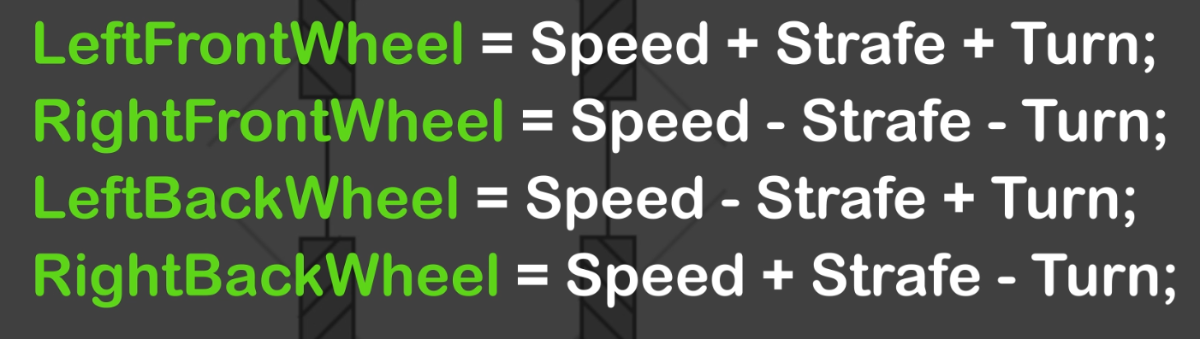
Using the same concept we can find forces in all directions and at the end, we will get four equations one for each wheel. These equations will help us in controlling the bot and are shown below.
How to use these equations ??
The answer is "joystick" I wrote an android app that works like a joystick. It has two sticks left side stick can move in both X and Y directions while the right side stick can only move in the X direction.
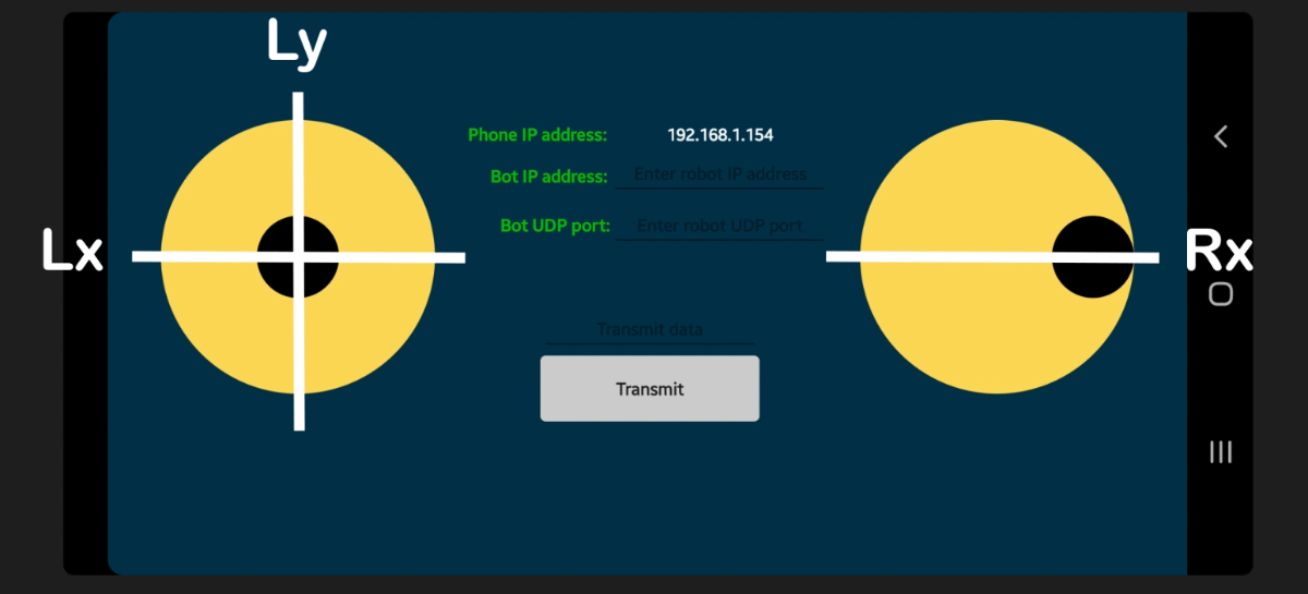
These sticks control the different variables of our control equation. If you move joysticks one at a time you will get very static movement to have some fun use both joysticks at the same time.
Ly
Controls speed which also means forward and backward
Lx
Controls strafe which means sliding left and right
Rx
Controls the turning of the robot around its geometrical center
A combination of all these parameters will allow you to control the robot in any direction. You don't have to worry about the equations because the motor speeds are calculated in the app itself. App uses these equations to calculate the speed and sends it to the robot over wifi.
You won't see these equations in the code of the robot because they are implemented in the app. For reference, the equation should be written like this.
Speed = Ly;
Strafe = Lx;
Turn = Rx;
LeftFrontWheel = Ly + Lx - Rx;
RightFrontWheel = Ly - Lx - Rx;
LeftBackWheel = Ly - Lx + Rx;
RightBackWheel = Ly + Lx - Rx;
There are much better ways to control the robot. This is the easiest one because the math is simple. I will implement better and faster methods in the next version. Please do not use this article for any serious work. This is a hobby project to know more about Mecanum wheels read some research papers.
ASSEMBLY
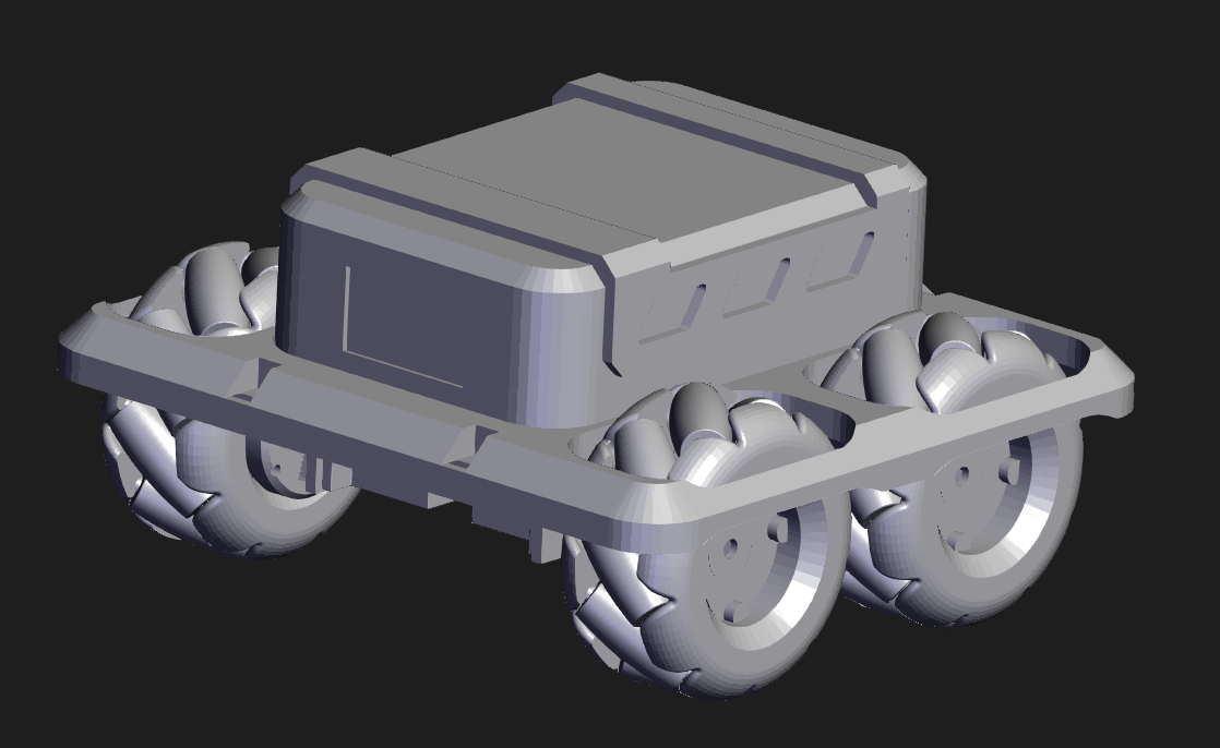
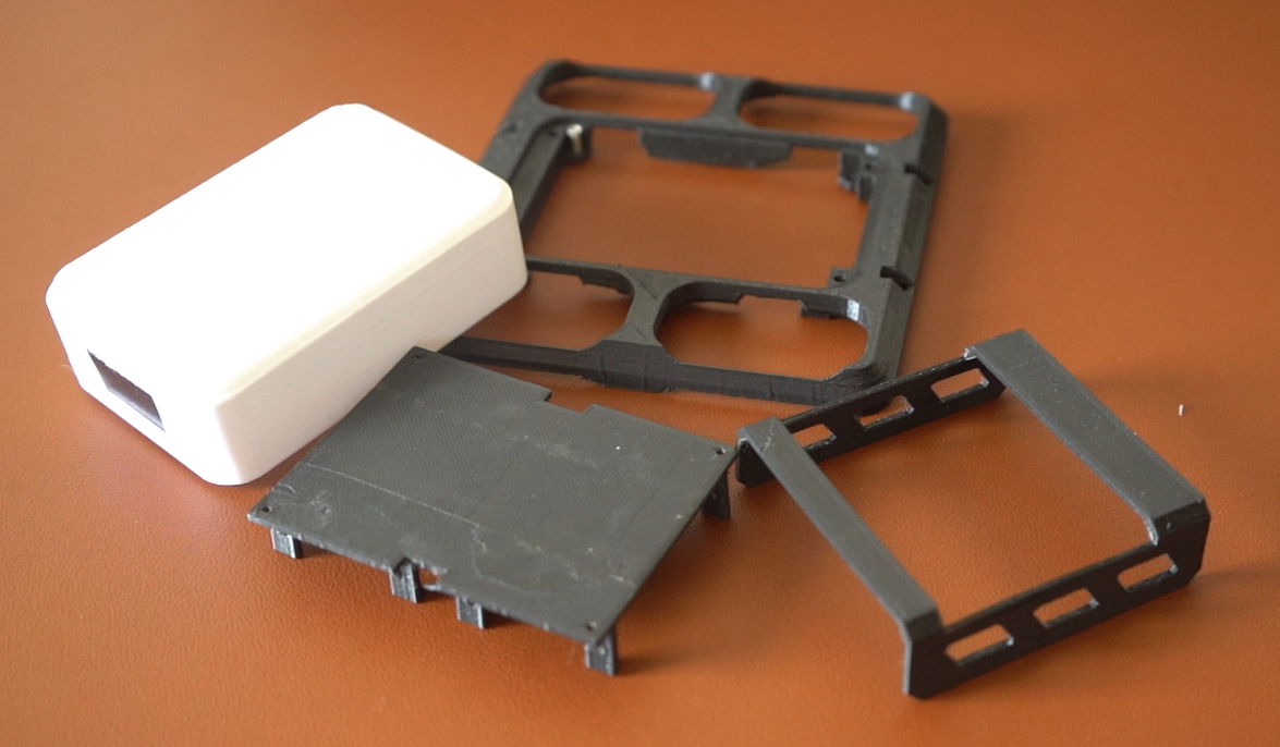
The whole project is 3D printed and all the files can be downloaded from the link below. There are only three 3D printing files so it is straightforward to assemble. Please use the explode feature on grabcad to see how every part fits.
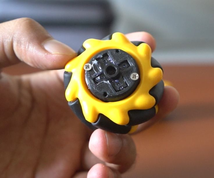
I'm using 2mm screws to join the complete chassis together and for attaching Motors to wheels I've designed a hub that can be screwed to the wheel. The Servo horn must be glued to the hub to make a good connection.
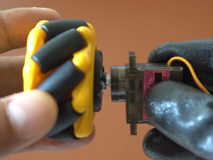
How to attach motors and wheel
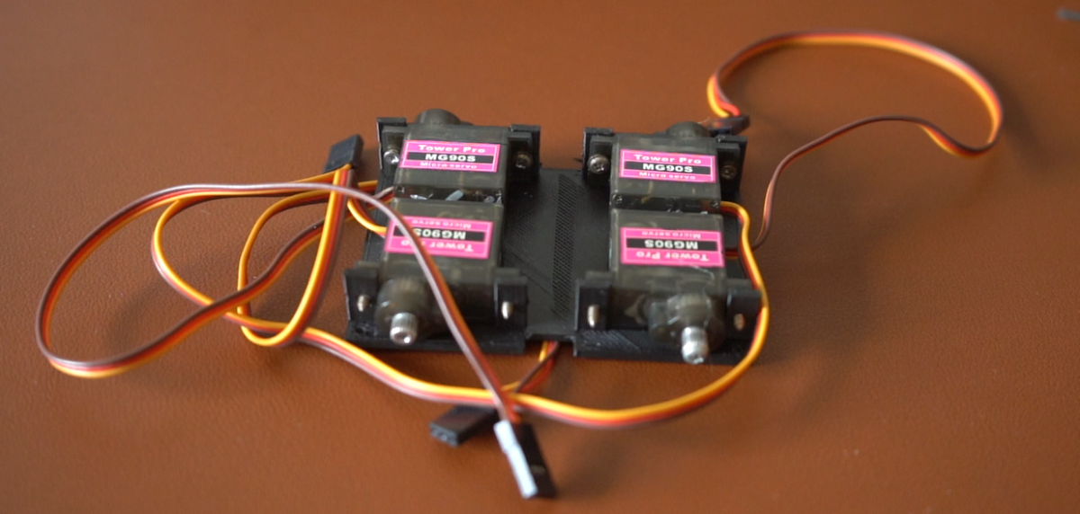
We will use 360 servos because they are easy to wire and Wemos does not have enough ports for two motor drivers. The walls are quite thin so be careful not to put too much pressure while screwing. I have included the raw CAD file of the model you can change it there if you like.
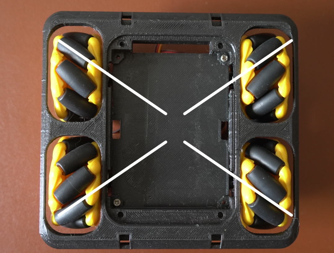
You cannot just attach any wheel to any position. Mecanum wheels are to be connected in a fixed pattern. Please refer to the image above.
ELECTRONICS
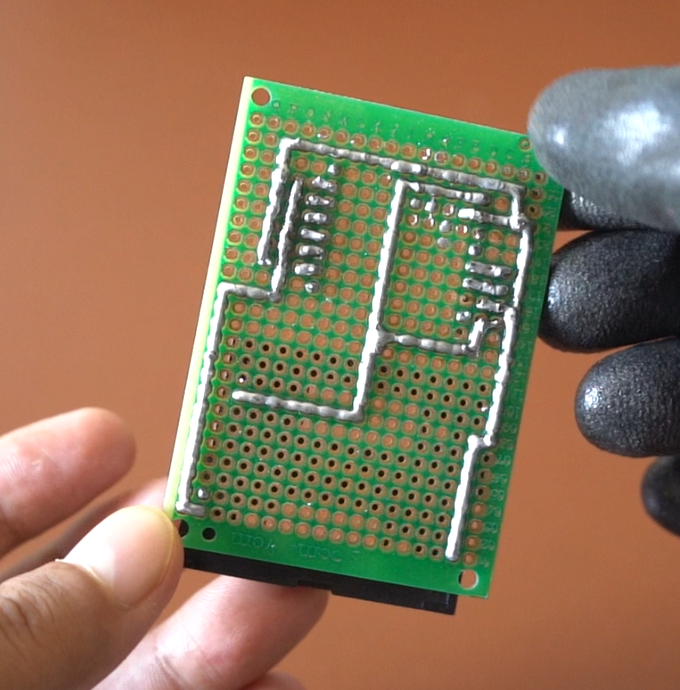
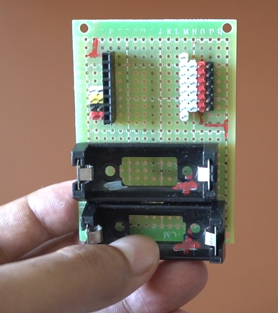
I am using a 5X7cm, generic perf board. We have two batteries one for Wemos and one for servos. They are not connected together they power them separately but you have to connect the ground wire of both to complete the circuit otherwise it will not work.
"REMOVE ALL POWER BEFORE CONNECTING TO THE PC JUST FOR SAFETY"
You can use any other ESP board if you like just change the pins inside the code. The program should work on most boards.
Circuit diagram
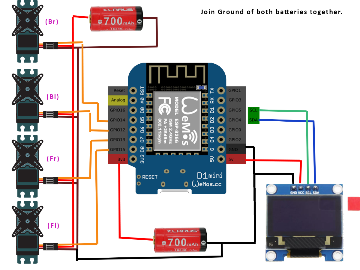
Please refer to the diagram above. I have marked the servos in the diagram and in the code also.
Fl = Front left wheel
Fr = Font right wheel
Bl = Back left wheel
Br = Back right wheel
Let's talk about screen
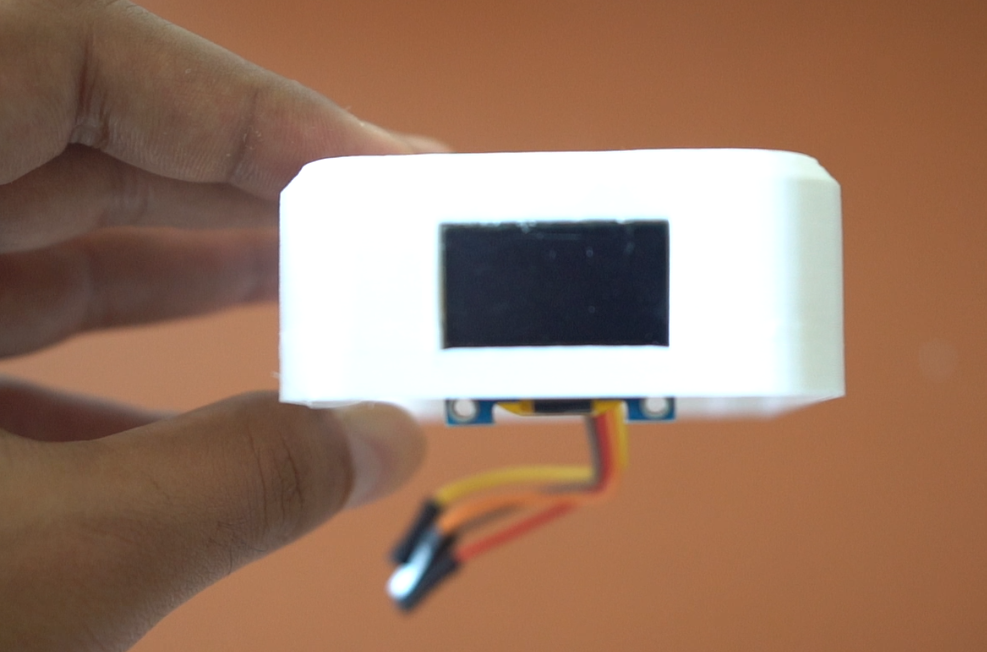
The screen is optional it just displays the eyes. Originally I wanted to do more with screens like displaying IP address and connection status maybe add some sensors and display graph but this project took a very long time to finish and I did not have any energy to add extra stuff maybe in the next version :)
Code
We will use Arduino to program the robot. By default, you won't see Wemos mini in Arduino. We have to add it to Arduino IDE. Please refer to this article on how to add ESP32 to Arduino IDE
Install these libraries before compiling the code.
#include <ESP8266WiFi.h>
#include <WiFiUdp.h>
#include <Servo.h>
#include <SPI.h>
#include <Wire.h>
#include <Adafruit_GFX.h>
#include <Adafruit_SSD1306.h>
Servo pins attach servos according to this also refer to the circuit diagram.
 fl.attach(15);//d8-Forward left
 fr.attach(D7);//Forward right
 bl.attach(D6);//Back left
 br.attach(D5);//Back right
Change your wifi name and password according to your wifi hotspot. Both robot and phone should connect to the same hotspot.
// Set WiFi credentials
#define WIFI_SSID "SINGTEL-42E6" //Wifi name
#define WIFI_PASS "huiweimaev" //Wifi password
#define UDP_PORT 4210 //UDP port name
The robot receives the commands from the app for each wheel and then maps the value to servos.
flss=map(sParams[0].toInt() ,-99,99,1000,2000);//Forward left wheel speed
frs=map(sParams[1].toInt() ,-99,99,1000,2000);//Forward right wheel speed
bls=map(sParams[2].toInt() ,-99,99,1000,2000);//Back left speed
brs=map(sParams[3].toInt() ,-99,99,1000,2000);//Back right speed
This function calls for various animations for the eyes. Don't be scared by the eyes part those are just random numbers we get after converting the image. The display does not have any practical use here you can ignore it if you don't have the budget.
void eyeMoves(){
 blink_eye();
 lookright();lookright();
 blink_eye();
 lookleft();lookleft();
}
Usually, you see four functions in these types of robot forward, back, left, and right but we have only two one is for stopping the motor and another one takes care of all the movements.
motor_forward() is actually a bad name because it is not just for forward direction this one function controls all direction movement because we pass the speed values as arguments. I am too lazy to change it :)
void motor_forward(int flss,int frs,int bls,int brs)
{
  fl.writeMicroseconds(flss);
  fr.writeMicroseconds(frs);
  bl.writeMicroseconds(bls);
  br.writeMicroseconds(brs);
 }
void motor_stop()
{
  fl.writeMicroseconds(1500);
  fr.writeMicroseconds(1500);
  bl.writeMicroseconds(1500);
  br.writeMicroseconds(1500);
  eyeMoves();
   }
You might see some additional stuff in the code that is not being used. Feel free to delete it and recompile the code if the robot is still working good job.
How to use the App
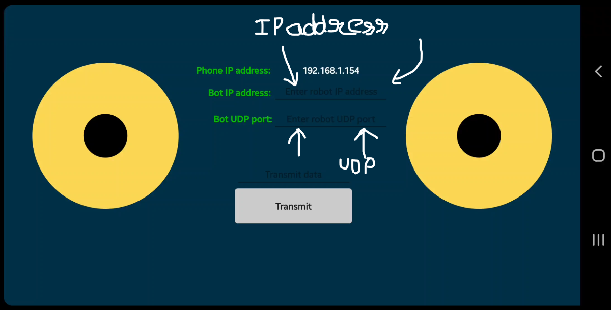
The android app is included in the code. After installing it you will see an interface like this. Both the bot and phone should be connected to the same wifi hotspot.
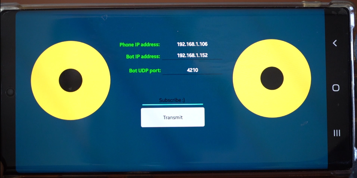
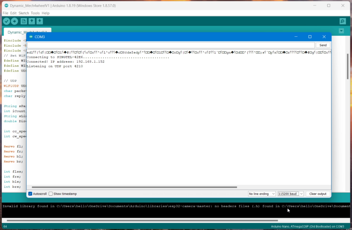
To connect to the bot you have to enter the bot IP address and UDP. To get the bot IP address upload the code to Wemos mini and while it is connected to the PC open the serial monitor by going to Tools > Serial monitor then change the baud rate to 115200 and press the reset button on the Wemos. You should see some text out on the serial monitor. If the bot has connected successfully you should see the IP address and UDP port. Note this down and enter it in the app. You should now be able to control the bot.
Conclusion
Ban Gaya robot maje karo and subscribe to my channel Saste jugaad
Akele-akele maje mat krna apne bhai ko bhi khilana and don't forget to tag me in your design.
You can contact me on Instagram or Discord if you need any help.