
This project is not just about coding. It combines cad modeling, maths, and UI design skills. This project is better if done with a small team so each member can focus on different aspects of the project. Someone might be good with design so they can work on the look of the control center or if someone likes maths they can change tweak how the values for graphs are processed and give out better reading.
----Before we start----
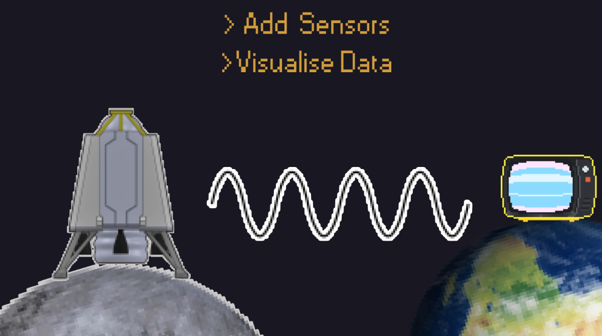
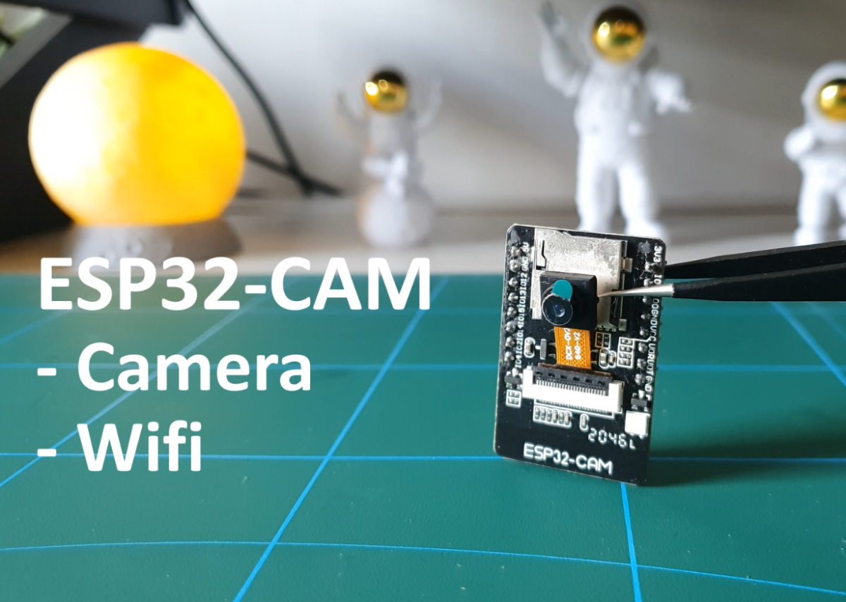
This is an open-source project which aims to inspire young students in the field of space and technology by simulating a small-scale moon mission. This is a multi-disciplinary project we don't just rely on software to do all the work. We have a physical model of lander which has various sensors like gyro, accelerometer, camera, and wifi. Lander can transmit data and video feed over wifi. On the other hand, we have our mission control center which is a program that receives the data sent from the lander just like a real moon mission. The Control center filters this data and applies some maths(High school level) to draw graphs and generate the rotation angles for the 3D model which represents the real state of the physical model. This project was designed for beginners and is user-friendly.
I have added some external links along with this tutorial for a better understanding of the concepts. Please go through those they cover almost everything you are going to need to make this project. If this is your first time it might take a week to complete this project.
Step 1: Building the Lander Model
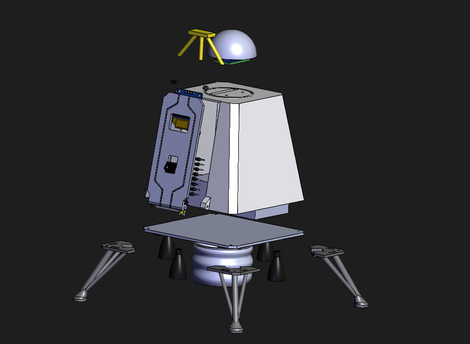
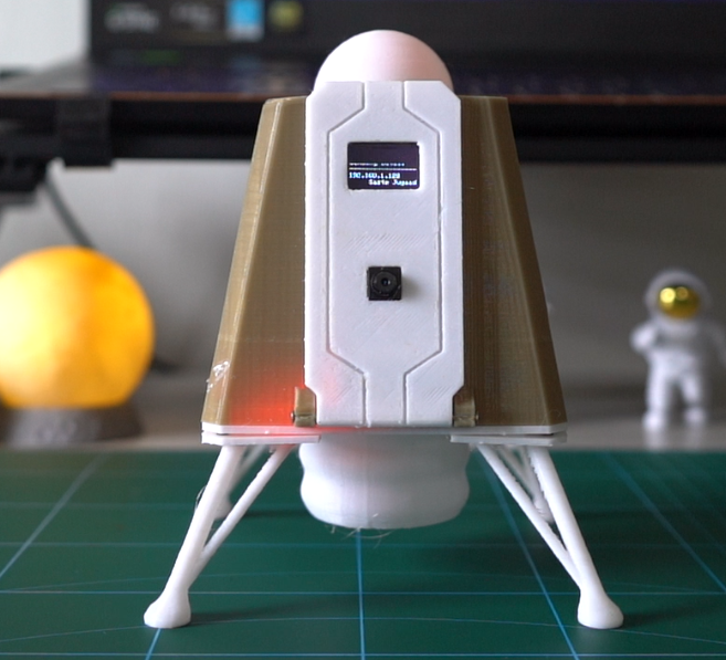
The design of the model is based on Vikram Lander by Indian Space Research Organisation. The spacecraft was launched on its mission to the Moon on 22 July 2019 However, the lander crashed when it deviated from its intended trajectory while attempting to land on 6 September 2019. I have given up a few details for easy 3Dprinting.
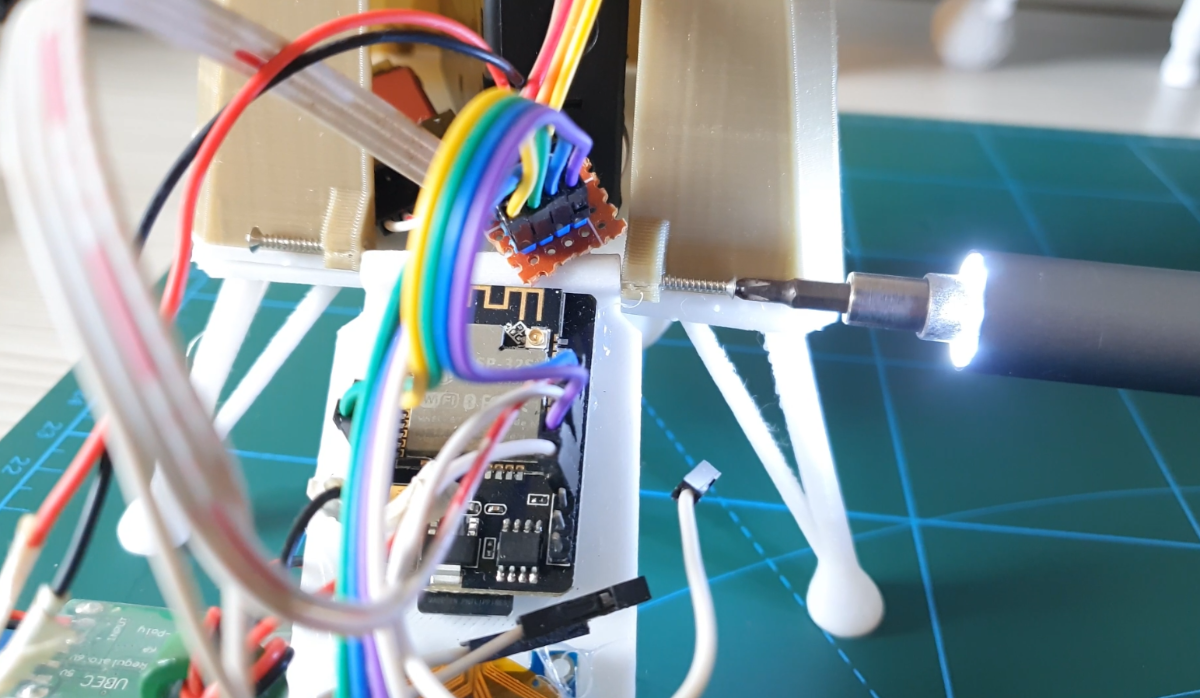
Lander model is 3D printed. You will need a glue gun to stick the legs. Using screws for everything was making the model complicated and increased the 3D printing time so it's easier this way. All files can be downloaded from grabcad.
Grabcad has a neat feature to let you see and explode the full 3d model on the browser itself. Please use it if you get confused about how to assemble the lander.
Note:-
If you do not have access to a 3D printer no problem you can use a plastic coca-cola botel cut it in the middle and paint from outside. Electronics don't take up that much space. Just make sure you stick the sensor firmly otherwise it will have false readings. Cardboard is also a good alternative.
Step 2: Sensors > MPU-6050 and Oled Screen
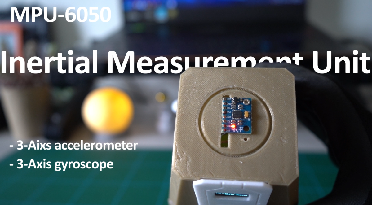
MPU6050 sensor module is a complete 6-axis Motion Tracking Device. It combines 3-axis Gyroscope, 3-axis Accelerometer, and Digital Motion Processor all in a small package. it has the additional feature of an on-chip temperature sensor. It has an I2C bus interface to communicate with the microcontrollers.
So this one small sensor takes care of everything we don't need any other sensor.
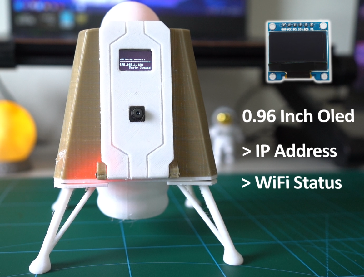
We also have an OLED screen to display information like IP address and connection status. When you power up the lander you will see various messages displayed on it as it checks for wifi connection and MPU6050. If everything is ok you will see the final screen as shown above. It will show an error message if anything is wrong. Think of it as a console. You can display any image on it.
Here are a few tutorials to help you get familiar with it.
Step 3: Installing Libraries
Before compiling and uploading the program we need to install the libraries for both Arduino and Processing IDE. Most of them can be found by simply searching on the library manager. Here are some links to help you install everything.
Arduino
https://www.arduino.cc/en/Guide/Libraries?setlang=en
https://www.digikey.com/en/maker/blogs/2018/how-to-install-arduino-libraries
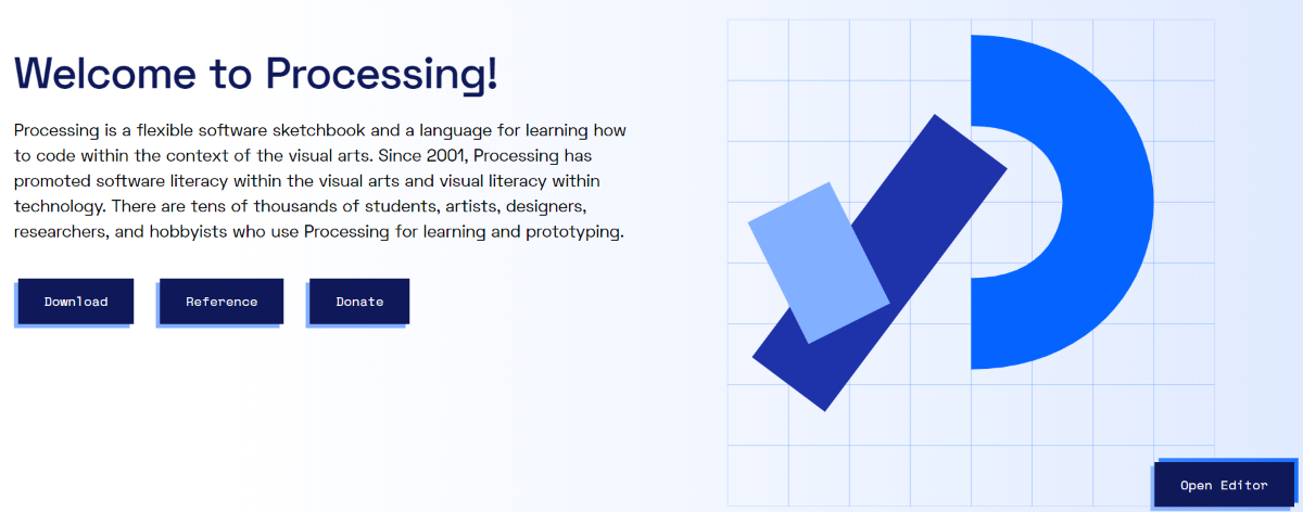
Processing
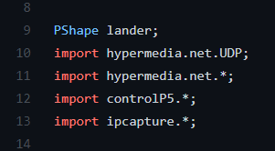
However not all the libraries are present in the library manager. Some of them you will have to install manually by copying them to the documents folder. I have given the list for all libraries above please install them and all the external libraries are listed below.
Arduino
Processing
Step 4: Wiring
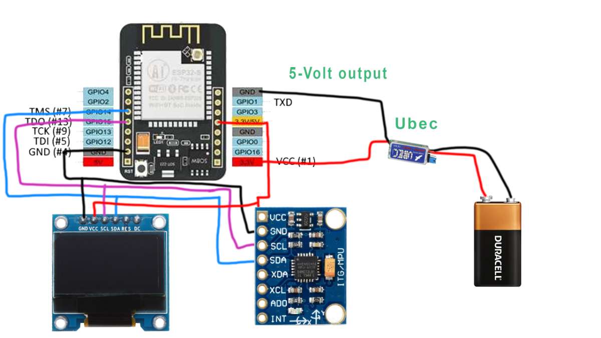
Wiring is very simple. Both MPU6050 and Oled screen use an I2C bus and have to be connected to the same pins. You will need a pinout diagram of esp32 to this. We will not use default I2C pins on esp32 instead we will use software I2C bus pin(14,15). For some reason, default I2C pins were not working on mine so I choose this method. Please refer to the diagram above.
Battery and Power
Everything runs on 5-volts however there is no 5-volt battery unless you are using a power bank. Most people will use a 9V battery but you cannot power the board directly with it you will fry the board. So we need to step down the voltage to 5Volts using a small converter or a buck.
You can use a 3-Volt Ni-cad battery also to power the whole thing.
--------DO NOT GO ABOVE 5VOLTS---------
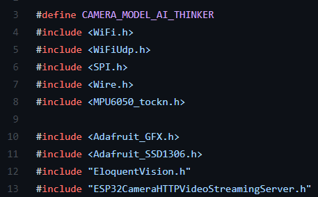
Step 5: Programming ESP32-CAM
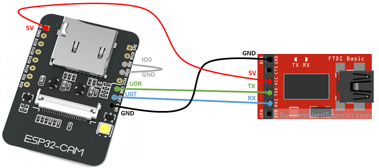
ESP32-CAM works like an Arduino but it's a little tricky to program because it does not have a USB port on board so we will have to use a programming cable. ESP32-CAM is also not listed on the default board list on Arduino software so we will have to add it there. So please follow the link below on how to do all this.
Install ESP32 boards on Arduino IDE
Step 6: Control Center
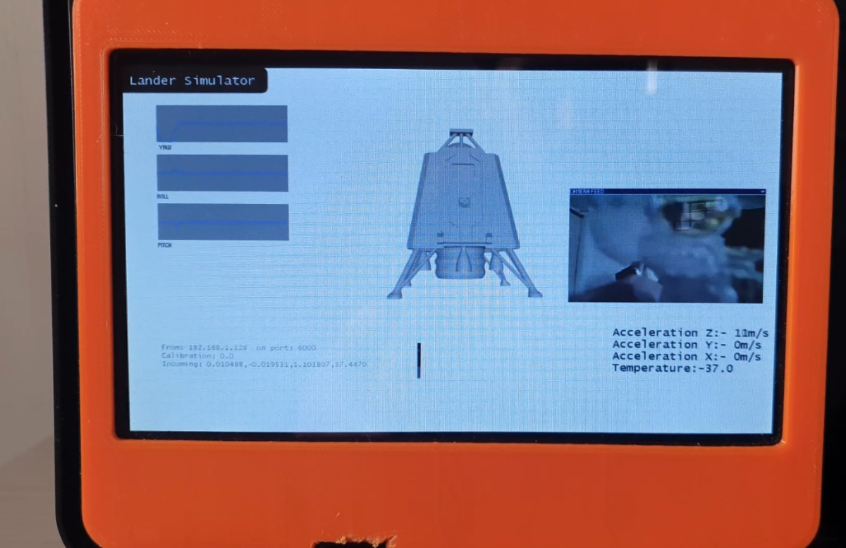
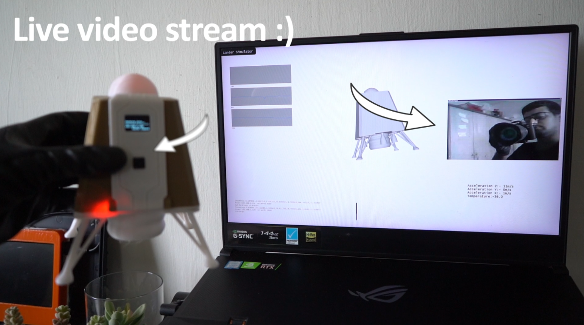
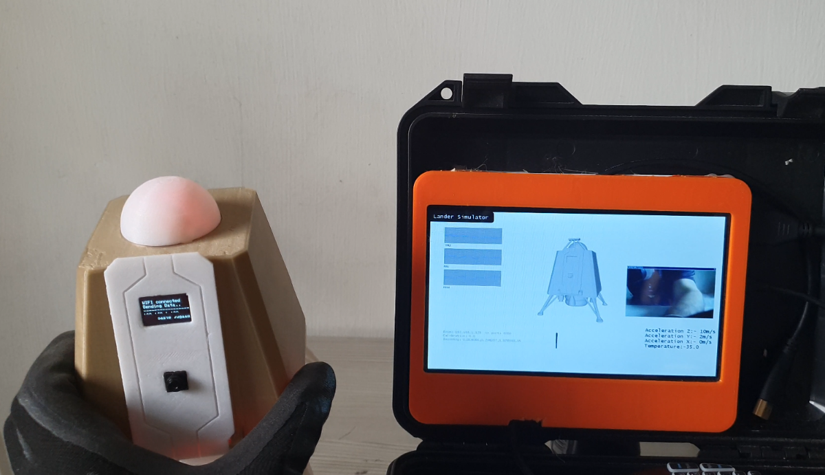
The control center works as a real mission center. It receives data from the lander through wifi and then uses that data to draw the graphs and 3d model of the lander representing the real state of the lander. It is written using processing which is very easy to understand.
Code is heavily commented the main library used in processing sketch is controlP5 all the graphs and numbers displayed on the screen are through this. Please read the code on Github for a better understanding. However, I will cover some basic stuff here.
Make sure both PC and Lander are connected to the same wifi. Internet is not needed. If there is any problem with getting the data in try tuning off the antivirus and firewall. Also, try different UDP addresses.
udp = new UDP( this, 6000 ); // change the port number here eg:- 5000,6000 etc.
You can replace the 3D model with anything you want.
- Put your model in the same directory as the Control center program
- Change the name of the loadShape() object to your model.
lander = loadShape("LanderV1.obj"); //loads 3D model of the lander
This part of the processing sketch receives the data as a single line then separate individual value into an array by using commas present in the line
 data = subset(data, 0, data.length);
	  String message = new String( data );
	  String[] list = split(message, ',');
Angles are received in degrees and need to be converted to radians before applying rotation to the 3D model.
  //convert angles to radians
	  rotateX(-Euler[2]*3.14/180);
	  rotateZ(Euler[0]*3.14/180+calib*3.14/180);
	  rotateY(Euler[1]*3.14/180);
Step 7: Code for Lander
Code is heavily commented on and can be downloaded from GitHub.
Please make the following changes to make it work with your wifi network.
// WiFi network name and password:
	//Change this to connect to your wifi router
	const char * networkName = "Askey5100-02B0";
	const char * networkPswd = "HHLUnKLKQW";
Change this to the IP address of the PC running the Control center program. Otherwise, the lander will not know where to send the data and the Control center will be blank.
//IP address to send UDP data to:
	// either use the ip address of the server or
	// a network broadcast address
	const char * udpAddress = "192.168.1.197"; //Ip address of the lander change this to your address
	const int udpPort = 6000;
Lander also acts as a Hotspot. The IP address of the lander is displayed on the Oled screen. You can use this IP address to get a live video stream on any web browser. There are two ways to connect either you connect your PC to the lander hotspot or connect both of them to the same external wifi network.
WiFi.softAP("ESP32", "12345678");// Lander hotspot SSID and password
This is the most important line as it defines how the data is sent over the network. Data is sent as a single line separated by commas. Processing sketch then reads this line and separates each value with the help of a comma. These values are then stored in an array. To add anything extra you just add the variables below and then increase the array size on the processing sketch.
udp.printf("%f,%f,%f,%f,%f,%f,%f",AccX,AccY,AccZ,temperature,yaw,roll,pitch);// Sends the data over wifiStep 8: How to Make It Work
Make sure everything is connected to the same network and you have entered all the IP addresses and port numbers correctly. I normally make a hotspot on my android phone and connect everything to it makes getting the IP address easier.
If you don't know how to find an IP address please use the following links
There is a sequence you need to follow. If you start the processing sketch before the lander there will be no incoming data so the sketch will give an error.
- First power up the lander
- Now start the processing sketch
Please make sure all wires to sensors are connected properly otherwise it gives annoying errors even if everything seems to be connected properly.
Basic working
- ESP32 reads data from MPU6050
- Packs it in one line separated by commas and sends it over the network.
- The processing sketch or control center reads this line then separates this data into an array.
- It uses commas to separate each reading.
- This new array is used to draw the graphs.
- Rotation angles received are used to rotate the 3D lander model.
Step 9: Conclusion
Please feel free to ask questions in a comment. There are multiple things happenings at the same time so I am sure you will run into some annoying situations. Please be patient good things take time.
This is not the end of this project I aim to build a small-scale lunar mission with rover and lander in the future all desktop size. This is just the start there is still a lot more that can be done with this project.
The live video stream can be accessed by a python program. You can do all types of computer vision stuff like mapping an area object detection e.t.c. ESP32 also has SD card support so you can save data into excel sheets, save video and images onboard the lander itself. Due to time constraints, I have kept the tutorial short but in the next version, I will implement all these ideas and more.
Enjoy your tiny lunar mission :)